Removal and Installation Procedures
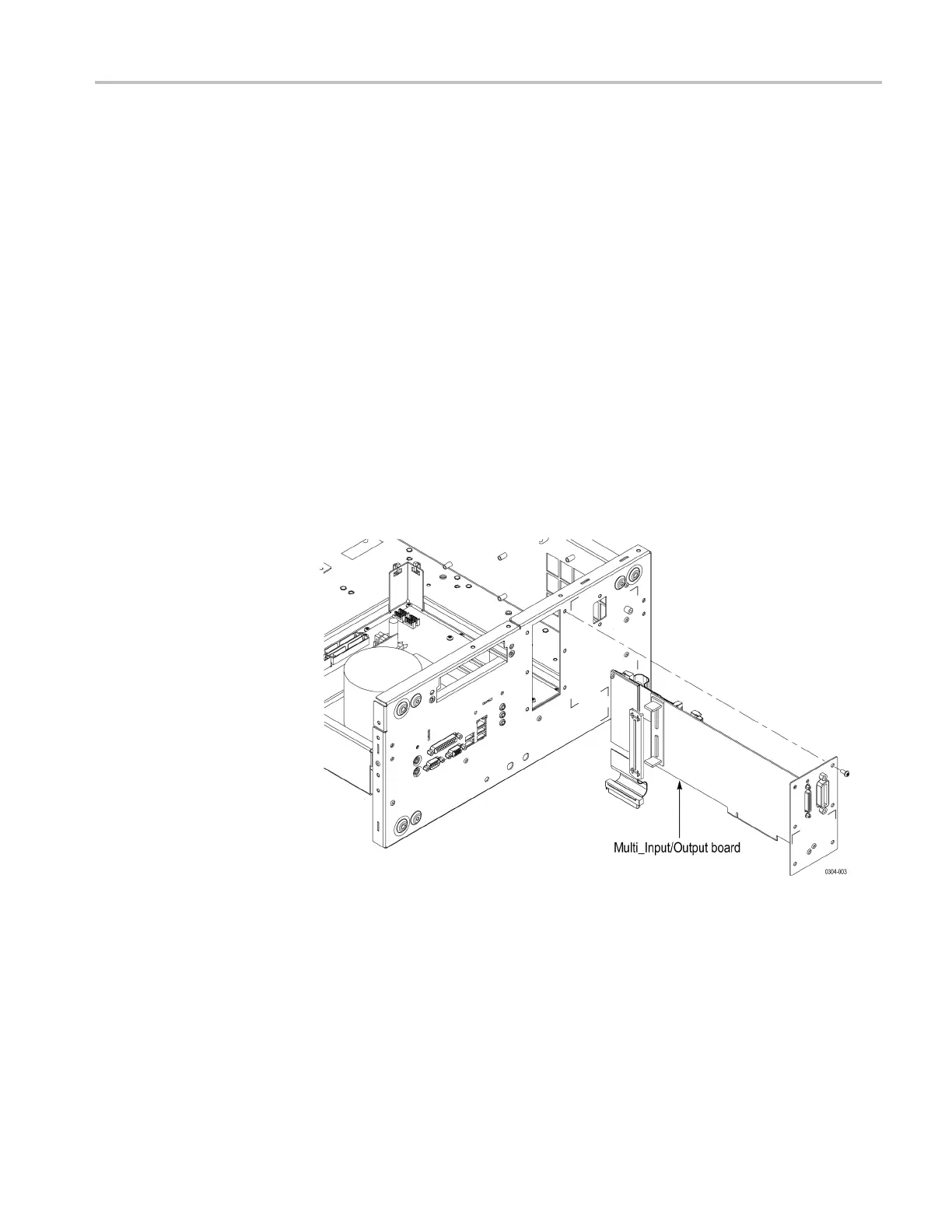
Multi-Input/Output Board
Youneedascrew
driver with a T-15 Torx tip (items 1 and 2).
Removal. To remove the Multi-Input/Output (MIO) board, follow t hese steps:
(See Figure 4-15.)
1. Remove the handle unit, snaps, cosmetic covers, front-trim unit, EMI covers,
hard disk assembly, and drive-bay module.
2. Orient the instrument so that the bottom is on the work surface and the rear is
facing you.
3. Disconnect the cables from J360, J600, J670, and J680 on the MIO board.
4. Remove the six screws securing the MIO board to the chassis.
5. Carefully pull up on the board to loosen it from the Processor board.
6. Lift the
circuit board and pull it through the rear of the chassis.
7. Remove the rear bracket and hardware from the circuit board.
Installation. To install, reverse this procedure.
Fi
gure 4-10: Multi-Input/Output board removal (AWG7000C Series)
AWG7000B and AWG7000C Series Service Manual 4–23

 Loading...


