Home
Tektronix
Test Equipment
DPO5204
Tektronix DPO5204 User Manual
4
of 1
of 1 rating
213 pages
Give review
Manual
Specs
To Next Page
To Next Page
To Previous Page
To Previous Page
Loading...
Install
Y
our
Ins
trument
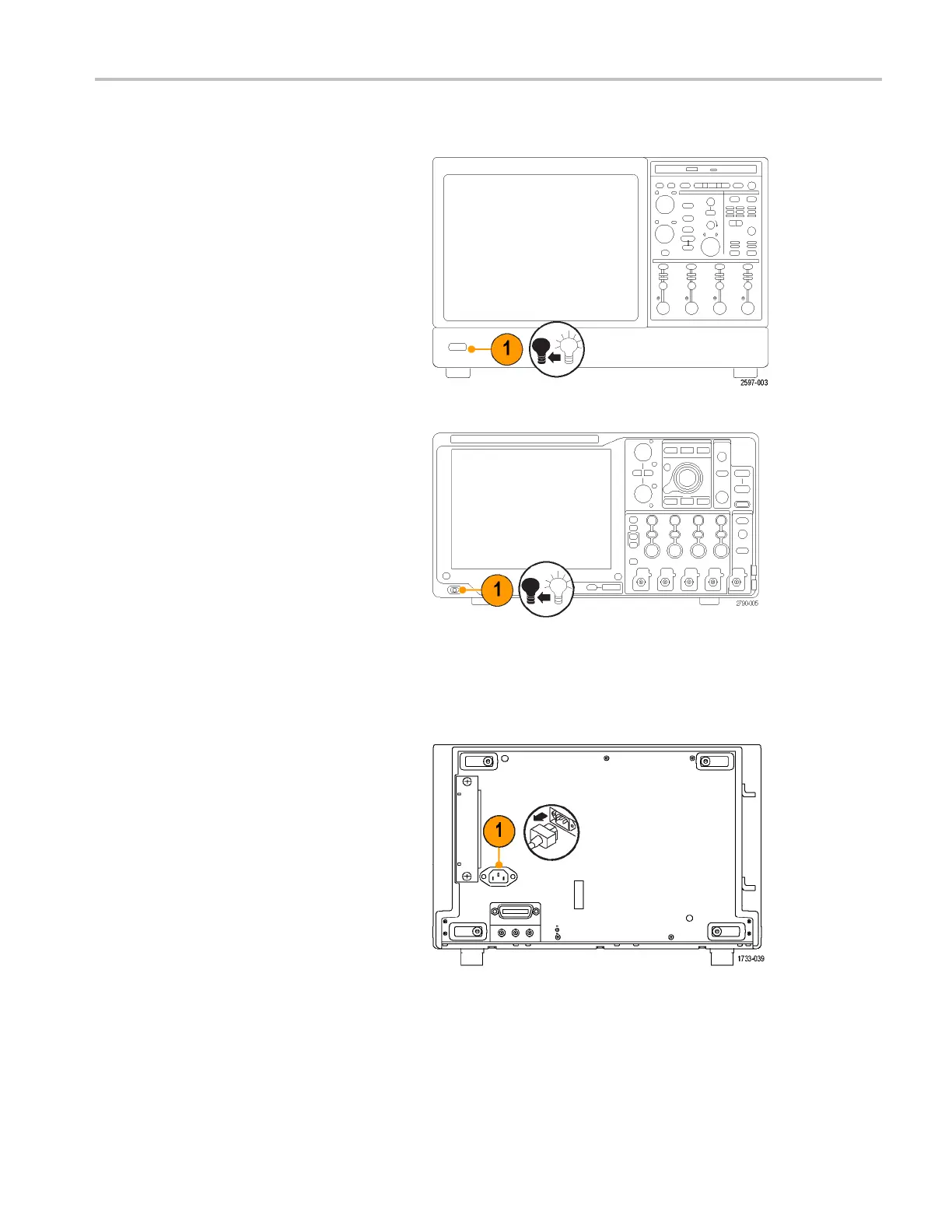
Powering
Off
the
Instrument
MSO70000/C,
DSA70000B/C
,
DPO7000
0B/C
,
and
DPO7000
Series
MSO5000
and
DPO5000
Series
Removing
the
Power
DPO7000
Series
MSO70000/C,
DPO/DSA70000B/C,
DPO7000,
and
MSO/DP
O5000
Series
U
ser
M
anual
7
27
29
Table of Contents
Table of Contents
8
General Safety Summary
12
Compliance Information
14
EMC Compliance
14
Safety Compliance
16
Pollution Degree
17
Overvoltage Category
17
Environmental Considerations
18
Preface
19
Key Features
19
Documentation
21
Conventions Used in this Manual
21
Install Your Instrument
22
Standard Accessories
22
Operating Requirements
23
Preventing ESD
26
Powering on the Instrument
26
Powering off the Instrument
28
Removing the Power
28
Securing the Oscilloscope
29
Connecting to a Network
30
Adding a Second Monitor
31
Operating System Restore
36
Installing the MSO5000 and DPO5000 Hard Drive
36
Getting Acquainted with Your Instrument
37
Front Panel
37
Side and Rear Panels
38
Interface and Display
42
Control Panel
44
Accessing Online Help
46
Accessing Menus and Control Windows
47
Inspect Your Instrument
49
Verify Internal Diagnostics Pass
49
Acquisition
50
Signal Path Compensation
50
Setting up Analog Signal Input
52
Using Default Setup
54
Using Autoset
55
Probe Compensation, Calibration, and Deskew
56
Acquisition Concepts
56
Waveform Record
58
How the Acquisition Modes Work
59
Changing the Acquisition Mode
60
Starting and Stopping an Acquisition
61
Selecting the Horizontal Mode
61
Using Fastacq
64
Using DSP Enhanced Bandwidth
66
Using Roll Mode
68
Setting up Digital Signal Input
69
Setting up Digital Channels
69
Setting up a Bus
71
When and Why to Turn on Magnivu
77
Using Magnivu
77
Viewing Analog Characteristics of Digital Waveforms
78
Using Fastframe Mode
80
Using Fastframe Frame Finder
82
Using Teklink and Multiscope Trigger
84
Pinpoint Triggers
88
Triggering Concepts
88
Trigger Coupling
89
Slope and Level
89
Choosing a Trigger Type
90
Trigger Selections
92
Checking Trigger Status
94
Using a (Main) and B (Delayed) Triggers
95
Triggering with B-Event Scan
98
Triggering on a Parallel Bus
101
Triggering on a Serial Bus
104
Sending E-Mail on Trigger
106
Setting up E-Mail on Event
107
Using Horizontal Delay
108
Display a Waveform
110
Setting the Display Style
110
Setting the Display Persistence
111
Setting the Display Format
112
Selecting the Waveform Interpolation
113
Adding Screen Text
114
Setting the Graticule Style
115
Setting the Trigger Level Marker
116
Displaying the Date and Time
116
Using the Color Palettes
117
Setting Reference Waveform Colors
118
Setting Math Waveform Colors
118
Using Multiview Zoom
118
Zooming in Multiple Areas
120
Lock and Scroll Zoomed Waveforms
122
Hide Waveforms in the Zoomed Window
123
Using Wave Inspector to Manage Long Record Length Waveforms
124
Searching and Marking Waveforms
126
Analyzing Waveforms
134
Taking Automatic Measurements
134
Automated Measurement Selections
136
Customizing an Automatic Measurement
139
Taking Cursor Measurements
142
Setting up a Histogram
144
Using Math Waveforms
146
Using Spectral Analysis
149
Using Mask Testing
152
Using Limit Testing
156
Myscope
158
Creating a New Myscope Control Window
158
Using Myscope Control Windows
162
Saving and Recalling Information
164
Saving Screen Captures
164
Saving Waveforms
165
Recalling Waveforms
167
Saving Digital Waveforms
168
Saving Instrument Setups
169
Recalling Instrument Setups
170
Saving Measurements
171
Saving User Masks
172
Saving Histogram Data
173
Saving Timestamps
174
Copying Your Results to the Clipboard
175
Printing a Hard Copy
176
Run Application Software
178
Application Examples
180
Capturing Intermittent Anomalies
180
Using the Extended Desktop and Openchoice Architecture for Efficient Documentation
184
Triggering on Buses
186
Triggering on a Video Signal
187
Correlating Data between a Tektronix Oscilloscope and Logic Analyzer
189
Appendix
190
Cleaning
190
Appendix
191
Obtaining the Latest Oscilloscope Application and Version Releases
191
Appendix
192
TPP0500 and TPP1000 500 Mhz and 1 Ghz 10X Passive Probes Instructions
192
Operating Information
192
Connecting the Probe to the Oscilloscope
192
Compensating the Probe
193
Standard Accessories
193
Optional Accessories
195
Replacing the Probe Tip
195
Specifications
195
Performance Graphs
196
Safety Summary
197
Appendix
199
P6616 General-Purpose Logic Probe Instructions
199
Product Description
199
Connecting the Probe to the Oscilloscope
200
Connecting the Probe to Your Circuit
201
Functional Check
201
Typical Application
202
Accessories
202
Specifications
203
Safety Summary
204
Safety Terms and Symbols in this Manual
204
Contacting Tektronix
205
Warranty Information
205
4
Based on 1 rating
Ask a question
Give review
Questions and Answers:
Need help?
Do you have a question about the Tektronix DPO5204 and is the answer not in the manual?
Ask a question
Tektronix DPO5204 Specifications
General
Brand
Tektronix
Model
DPO5204
Category
Test Equipment
Language
English
Related product manuals
Tektronix DPO5204B
222 pages
Tektronix DPO5104
213 pages
Tektronix DPO5054
213 pages
Tektronix DPO5034
213 pages
Tektronix DPO5104B
222 pages
Tektronix DPO5054B
222 pages
Tektronix DPO5034B
222 pages
Tektronix DPO5000 Series
1002 pages
Tektronix DPO2012
272 pages
Tektronix DPO2024
272 pages
Tektronix DPO4034
359 pages
Tektronix DPO2024B
152 pages
 Loading...

