OPERATION
79
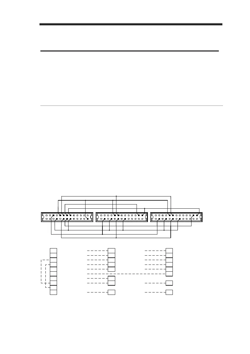
Master-Slave Parallel Connection
The Analog Control Connector is used for both
serial and parallel connections. The way the
connector is configured determines the
behavior of the master and slave units. For the
complete connector pin assignment, see page
123.
Analog Connector
Connection
To operate the power supplies in parallel,
connect the analog connectors on the master
and slave units as shown in the diagrams
below.
Alternatively pre-configured cables (optional)
can be used. The 2260B-006 is used for two
units in parallel. The 2260B-007 is used for 3
units in parallel.
Master with 2 slave units:
12
13
14
1517
20
21
24 20 12
17 15 3 17 15
312
24 20
11 1
2
1
OUTPUT ON STATUS21
Master unit
ALM STATUS20
STATUS COM17
FEEDBACK15
CURRENT_SUM_113
SHUTDOWN12
OUT ON/OFF CONT24
Slave Unit 1
12 SHUTDOWN
20 ALM STATUS
15 FEEDBACK
3 CURRENT SUM OUT
Slave Unit 2
OUT ON/OFF CONT24
12 SHUTDOWN
17 STATUS COM 17 STAT US COM
2 D COM
15 FEEDBACK
CURRENT_SUM_2 CURRENT SUM OUT314
20 ALM STATUS
11 1 1I MON CURRENT SHARE CURRENT SHARE
16 16 16
A COM16 16 A COM 16 A COM

 Loading...


