A Tour of Your Instrument
8. Dedicated RF in
put with N-connector
9. Analog channel (1, 2, (3, 4)) inputs with TekVPI versatile probe interface
10. Digital channel input
11. Display: shows frequency or time domain
12. Arbitrary waveform generator (AFG) enable button
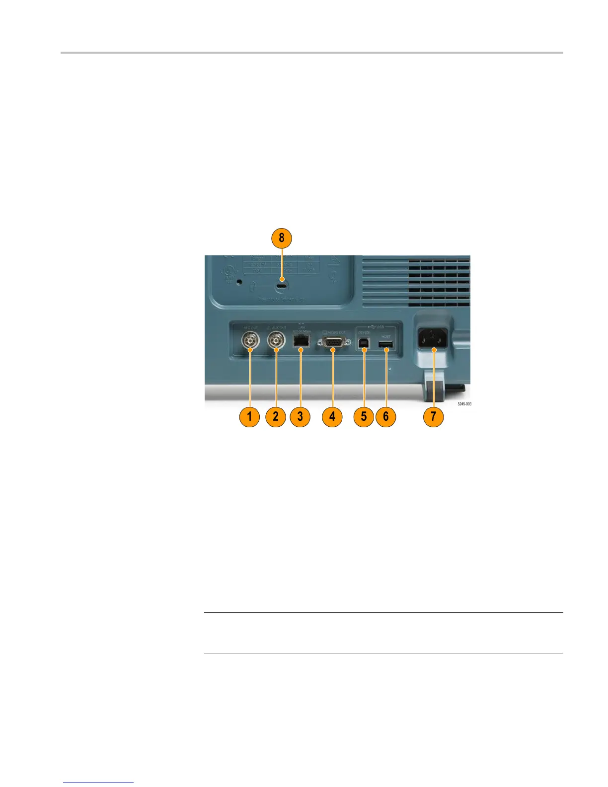
Rear-Panel Connectors
1. AFG OU
T. Use the AFG OUT port to transmit signals from the arbitrary
function generator.
2. AUX O
UT
3. LAN. Use the LAN (Ethernet) port (RJ-45 connector) to connect the
osc
illoscope to a 10/100 Base-T local area network.
4. Video Out. Use the Video Out port (DB-15 female connector) to show the
osc
illoscope display on an external monitor or projector.
5. USB 2.0 Device port. Use the USB 2.0 High Speed Device port to connect
aP
ictBridge compatible printer, or for direct PC control of the oscilloscope
using U SBTMC protocol.
NOTE. The cable connected from the USB 2.0 Device port to the host computer
must meet the USB2.0 specification for high speed operation when connected to
a high speed host controller.
MDO3000 Installation and Safety Instructions 21

 Loading...


