Input signal requirements
Keep the input signals within allowed limits to ensure the most accurate measurements and prevent damage to the analog and digital
probes or instrument. Make sure that input signals are within the following requirements.
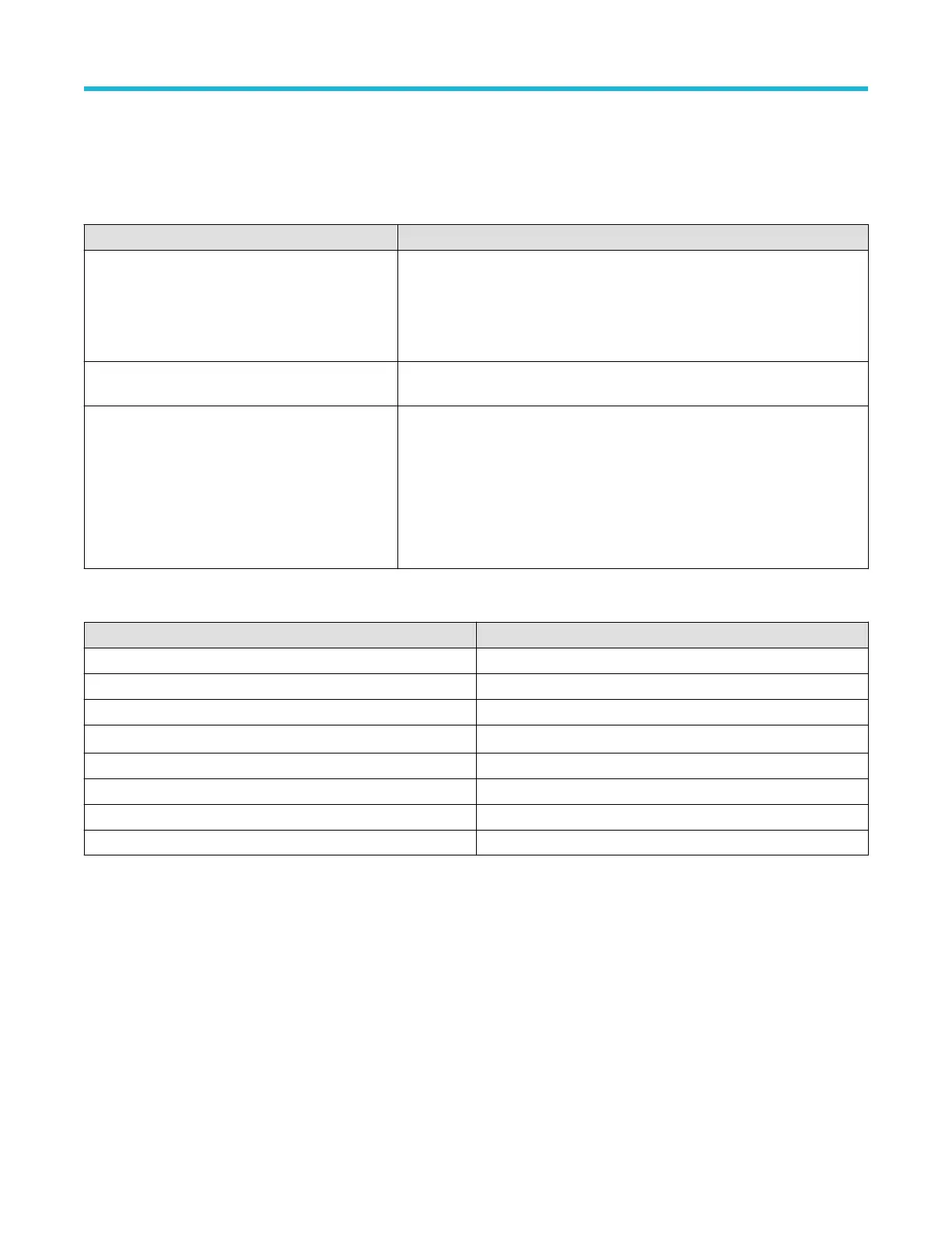
Table 1: Maximum analog input
Input Description
Analog input channels, 1 M Ω setting, maximum input
voltage at BNC
300 V
RMS
Measurement Category II
De-rate at 20 dB/decade between 4.5 MHz and 45 MHz, De-rate 14 db between
45 MHz and 450 MHz. Above 450 MHz, 5 V
RMS
.
Analog input channels, 50 Ω setting, maximum input
voltage at BNC
5 V
RMS
with a peak at ±20 V
. (DF ≤ 6.25%).
RF input maximum input voltage Average Continuous Power: +20 dBm (0.1 W)
DC maximum before damage: ±40 VDC
Max no damage +33 dBm (2 W) CW
Peak Pulse Power: +45 dBm (32 W)
Peak Pulse Power defined as <10 μs pulse width, <1% duty cycle, and reference
level of ≥ +10 dBm
Table 2: Maximum input with a P6316 Digital Probe
Input Description
Threshold Accuracy ±(100 mV + 3% of threshold setting after calibration)
Threshold Range +25 V to –15 V
Maximum nondestructive input signal to probe +30 V to -20 V
Minimum signal swing 500 mV
peak-to-peak
Input resistance 101 kΩ
Input capacitance 8.0 pF typical
Pollution Degree 2, indoor use only
Humidity 5% to 95% relative humidity
Getting started
3 Series Mixed Domain Oscilloscope MDO32 and MDO34 Quick Start Manual 13

 Loading...


