Check that the oscilloscope passes power-on self tests
Power-on self tests verify that all oscilloscope modules are working correctly after power up.
Procedure
1. Power on the oscilloscope and wait until the oscilloscope screen appears.
2. Select Utility > Self T
est from the top-edge Menu bar to open the Self Test configuration menu.
3. Check that the status of all power-on self tests are Passed.
If one or more power-on self tests shows Failed:
a. Power cycle the oscilloscope.
b. Tap Utility > Self Test. If one or more power-on self tests still shows Failed, contact Tektronix Customer Support.
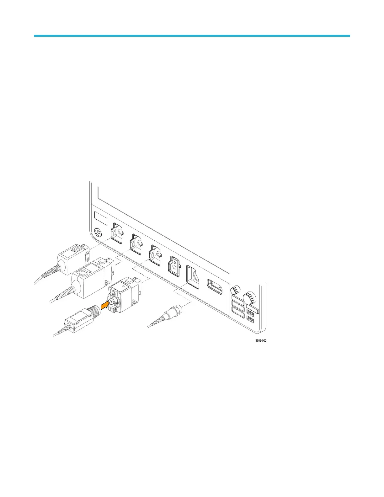
Connecting probes
Probes and cables connect the oscilloscope to your device under test (DUT). Use a probe that best matches your signal measurement
needs.
1. Tektronix Versatile Probe Interface (TekVPI). These probes support two-way communication with the oscilloscope through on-screen
menus and remotely through programmable support. The remote control is useful in applications like A
TE where you want the system
to set probe parameters.
2. Tektronix Versatile Probe Interface (TekVPI) for Passive Probes. These probes build upon the functionality of the TekVPI interface.
Each probe is matched with its corresponding oscilloscope channel, allowing the oscilloscope to optimize the signal input path. This
provides AC compensation across the frequency band.
3. TPA-BNC Adapter. The TPA-BNC Adapter allows you to use TEKPROBE II probe capabilities, such as providing probe power and
passing scaling and unit information to the oscilloscope.
4. BNC Interfaces. Some of these use TEKPROBE capabilities to pass the waveform signal and scaling to the oscilloscope. Some only
pass the signal and there is no other communication.
5. Logic Probe Interface. The P6316 probe provides 16 channels of digital (logical one or zero) information.
6. TPA-N-VPI Adapter. The TPA-N-VPI Adapter allows you to use TekVPI probes with the RF input.
Getting started
3 Series Mixed Domain Oscilloscope MDO32 and MDO34 Quick Start Manual 15

 Loading...


