7. Use Ground and probe compensation connectors to provide a ground connector to help reduce electrostatic damage (ESD) and adjust
the high-frequency response of a passive probe. The Ground and Probe Compensation connectors are located at the lower right side
of the instrument, near the front panel.
8. USB ports are located at the lower right corner of the front panel and on the rear panel. Connect USB flash drives to which you can
save or recall data (such as instrument software updates, waveforms, settings, and screen captures) or connect peripheral devices
such as a mouse or keyboard.
9. Use the Probe connectors to connect T
ekVPI+ and TekVPI measurement probes, BNC passive probes, the P6316 Logic Probe, and
BNC cables.
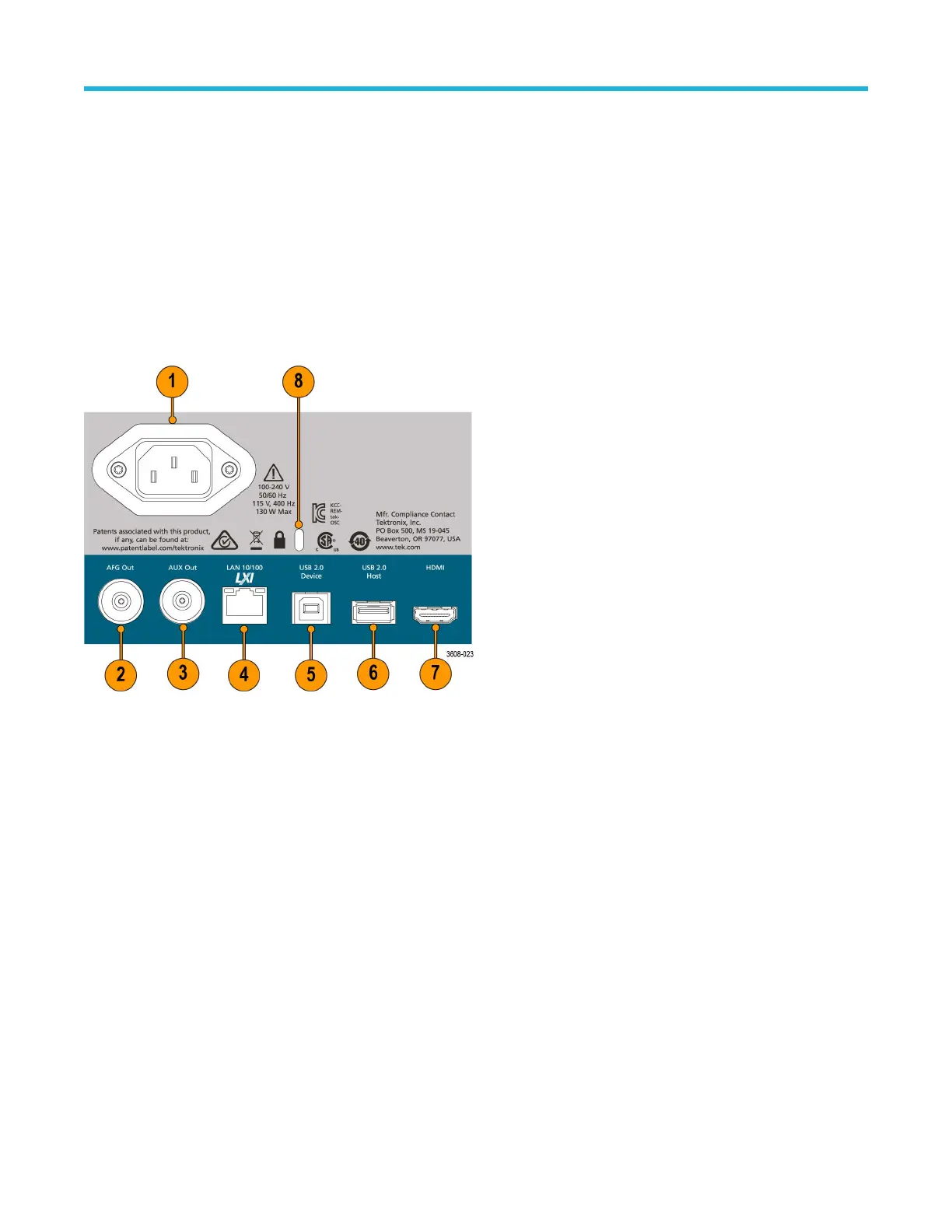
Rear panel connections
The rear panel connections supply power to the oscilloscope and provide connectors for network, USB devices, video, reference signals,
and the AFG output.
1. Power cord connector
. Use only the power cord specified for this product and certified for the country of use.
2. AFG Out is the signal output for the optional Arbitrary Function Generator (AFG) feature.
3. AUX Out generates a signal transition on a trigger event or outputs a synchronization signal from the AFG.
4. LAN connector (RJ-45) connects the oscilloscope to a 10/100 Base-T local area network.
5. USB Device port lets you connect to a PC to remotely control the oscilloscope using the USBTMC protocol.
6. USB Host port lets you connect a USB memory device, keyboard, or mouse.
7. HDMI output lets you connect an external monitor or projector to show the oscilloscope screen.
8. Security lock connector lets you use a standard PC/laptop lock cable to secure the oscilloscope to a work bench or other location.
Getting acquainted with your instrument
3 Series Mixed Domain Oscilloscope MDO32 and MDO34 Quick Start Manual 19

 Loading...


