Performance ver
ification
Channel amplitude flatness
The amplitude flatness test verifies amplitude at the two normalized bands and the band most likely to encounter a channel
response problem. The channel flatness is measured for 2 MHz – 42 MHz, 1260 MHz – 1300 MHz, and 2140 MHz
– 2180 MHz.
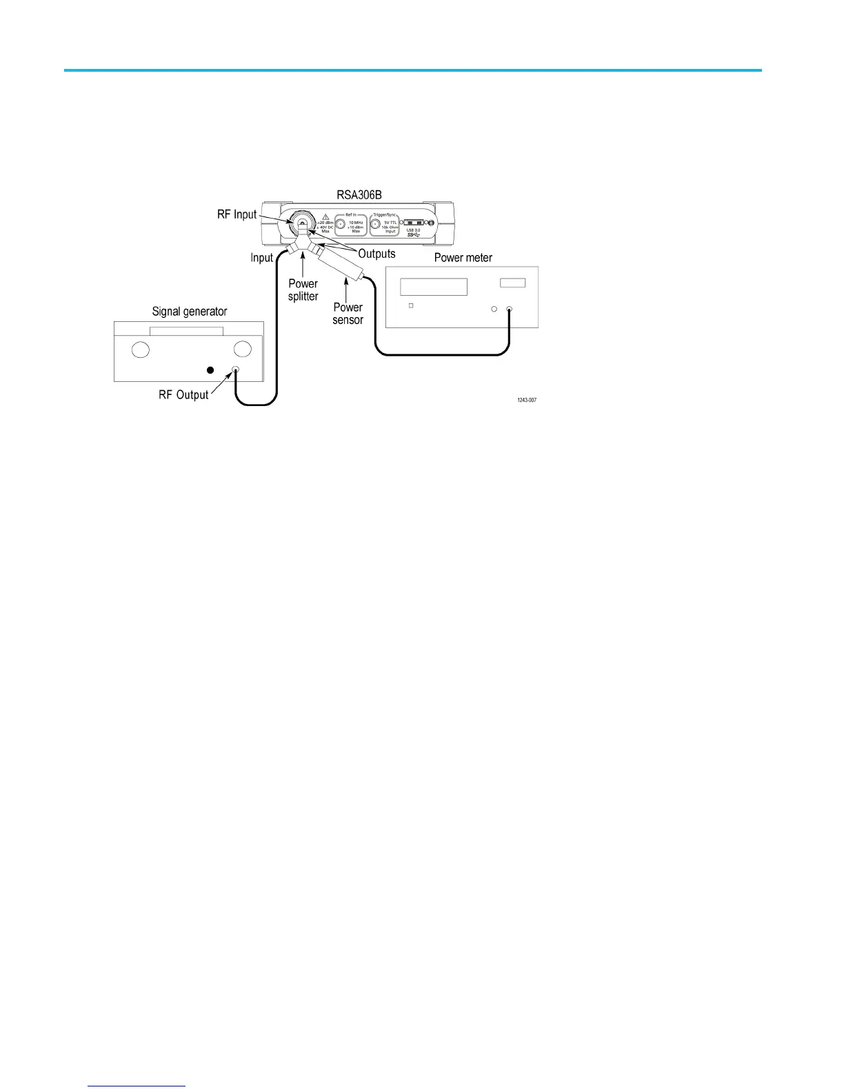
1. Connect the signal generator, power splitter, power sensor, power meter, and RSA306B as shown in the following figure.
Connect the power splitter outputs directly to the RSA306B RF Input and to the power sensor.
2. Reset the RSA306B to factory defaults (Presets > Main).
3. Run the RSA306B alignment procedure (Tools > Alignments > Align N ow).
4. Set the RSA 306B as follows:
a. Reference Level = 0dBm.
b. Detection = +PEAK (Setup > Settings > Traces > Detection > +PEAK).
c. Filter shape = Flat-Top (Setup > Settings > BW > Filter Shape > Flat-top).
d. Center Frequency = 22 MHz
e. Span = 40 MHz
f. RBW = Auto (300 kHz)
g. Function = Normal (Setup > Settings > Traces > Function)
5. Set the signal generator frequency to the first frequency in the 2 MHz – 42 MHz channel flatness table. (See Table 10.)
6. Set the signal generator amplitude for –5 dBm at the power meter and RSA306B.
7. Record the power meter reading in the 2 MHz – 42 MHz channel flatness table. (See Table 10.)
8. On the RSA306B, position the marker on the peak amplitude of the signal; record the amplitude in the channel flatness
table.
9. Repeat steps 5 through 8 to measure and record for all the frequencies in the channel flatness table, 2 MHz through
42 MHz. Do not change the RSA306B center frequency setting.
10. Set the RSA center frequency to 1280 MHz.. Keep other settings the s ame.
11. Set the signal generator frequency to 1260 M Hz .
26 RSA306B Specifications and Performance Verification

 Loading...


