Performance ver
ification
Input-related spurious response: ADC
Requirements:
An RF signal generator capable of at least 8 GHz (example: Stanford Research Systems S G386 Option 02)
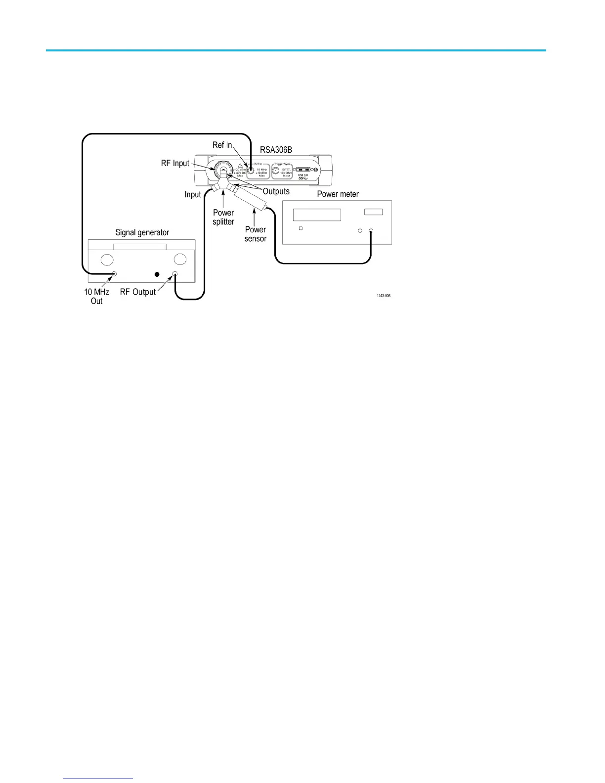
1. Connect the signal generator, power splitter, power sensor, power meter, and RSA306B as shown. Connect the power
sensor and RF signal generator directly to the power splitter, which is connected directly to the
RSA306B.
2. Reset the RSA306B to factory defaults (Presets > Main).
3. Run the RSA306B alignment procedure (Tools > Alignments > Align N ow).
4. Set the RSA 306B as follows:
a. Reference Level = –30 dBm
b. Span = 40 MHz
c. RBW = 1kHz
d. Detection mode = +PEAK (Setup > Settings > Traces > Detection > +PEAK)
e. Function = Avg (Vrms) (Setup > Settings > Traces > Function)
f. Averaging = 10 (Setup > S ettings > Traces > Function: set count = 10)
g. Select External Reference (Setup > Acquire > Frequency Reference > External)
LF ADC image.
5. Set the signal generator frequency to 21 MHz.
6. Set the signal generator output level for –30 dBm on the power meter. This amplitude is also at the RSA306B input (the
signal generator setting will be near –24 dBm).
7. Set the RSA306B center frequency to 21 MHz (40 MHz span).
8. Position the marker on the signal at 21 MHz.
9. Record the value in the ADC measurements table. (See Table 16 on page 40.) The amplitude will be near –30 dBm, but
may have some measurement error.
38 RSA306B Specifications and Performance Verification

 Loading...


