Performance ver
ification
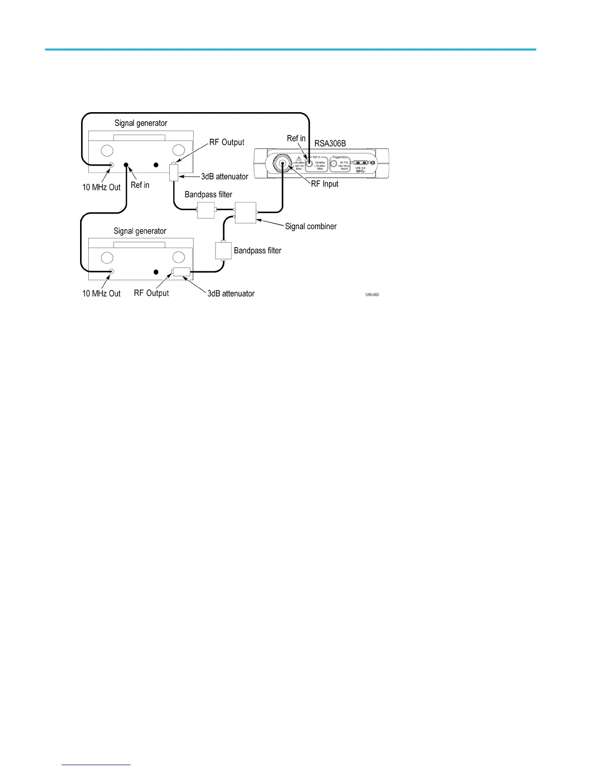
Third-order intermodulation distortion
Set up the RF signal generators, band-pass filters, signal combiner, and RSA306B as shown.
1. Reset the RSA306B to factory defaults (Presets > Main).
2. Run the RSA306B alignment procedure (Tools > Alignments > Align N ow).
3. Set the RSA 306B as follows:
a. Reference Level = –15 dBm
b. Span = 100 kHz
c. RBW = 1kHz
d. Detection mode = +PEAK (Setup > Settings > Traces > Detection > +PEAK)
e. Function = Avg (Vrms) (Setup > Settings > Traces > Function)
f. Averaging = 10 (Setup > S ettings > Traces > Function: set count = 10)
g. Select External Reference (Setup > Acquire > Frequency Reference > External)
4. Set one RF signal generator frequency to 2.1295 GHz. Set the second RF signal generator frequency to 2.1305 GHz.
5. Set each of the RF signal generators to provide a power level of –20 dBm each at the RSA306B. The initial generator
amplitude setting is should be -13 dBm, and the amplitude is fine-tuned as follows:
a. Set the RSA306B center frequency to 2.1295 GHz. M ove the marker to the largest amplitude. Adjust the first
generator output level for a marker reading of –20.0 dBm (±0.1 dB) (after averaging).
b. Set the RSA306B center frequency to 2.1305 GHz. Move the marker to the largest amplitude. Adjust the second
generator output level for a marker reading of –
20.0 dBm (± 0.1 dB) (after averaging).
6. Set the RSA306B center frequency to 2.1285 GHz. After averaging has completed, position the marker on the highest
amplitude trace point and read the marker amplitude. Record the IMD #1 amplitude. (See Table 15 on page 37.)
7. Set the RSA306B center frequency to 2.1315 GHz. After averaging has completed, position the marker on the largest
trace point and read the marker amplitude. Record the IMD #2 amplitude.
36 RSA306B Specifications and Performance Verification

 Loading...


