Performance ver
ification
Phase noise
The intent of the Phase N oise test is to measure the phase noise level of the instrument. The phase noise specification does
not cover residual spurs. If the specific measurement frequency results in measuring a residual spur that is visible above the
noise level, the phase noise specification applies not to the spur but to the noise level on either side of the spur. Please
refer to the Spurious Response specifications. Also, refer to the Spurious Response section of this procedure to determine
whether or not a residual spur is within the speci fication.
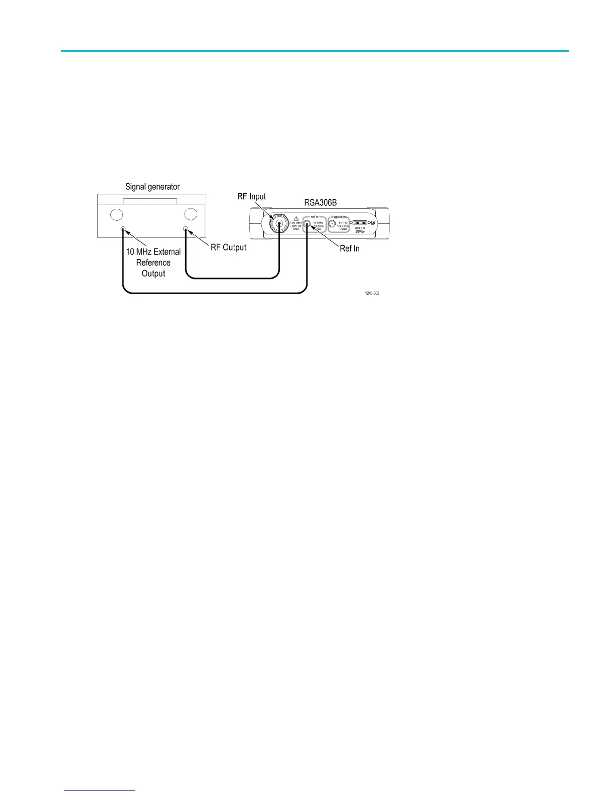
Connect the signal generator and RSA306B as shown in the following figure.
1. Reset the RSA306B to factory defaults (Presets > Main).
2. Run the RSA306B alignment procedure (Tools > Alig nments > A lign Now). Note: the Center frequency should be
1GHz.
3. Set the signal generator CW frequency = 1GHz.
4. Set the signal generator CW amplitude = 0dBmat the RS306 input.
5. Select External Reference (Setup > Acquire > Frequency Reference > External)
6. Set trace detection = +PEAK (Setup > Settings > Traces > Detection)
7. Measure the CW amplitude for the following settings:
a. Trace Function = Avg (Vrms), 10 averages (Setup > Settings > Traces > Function: Avg (Vrms
), count = 10)
b. Span = 100 kHz
c. RBW = 1kHz
d. Move MR marker to highest amplitude signal after 10 averages, write the marker value as the CW amplitude (for the
1kHzfilter) in the measurement table. (See Table 14.)
8. Measure the CW amplitude for the following settings:
a. Span = 10 kHz
b. RBW = 100 Hz
c. Move MR marker to highest amplitude signal after 10 averages, write marker value as the CW amplitude for the
100 Hz filter and 10 Hz filter in the measurement table. (See Table 14.)
9. Set Trace detection = Avg (Vrms).
10. Set Marker function = Power (dBm/Hz) (Markers > Define Markers > Readouts (near bottom of w indow) > Power).
11. Turn on marker (Markers > Define Markers > Add)
RSA306B Specifications and Performance Verification 33

 Loading...


