Maintenance
6-- 4
TDS1000B and TDS2000B Series Oscilloscope Service Manual
To access the inside of the oscilloscope for inspection and cleaning, refer to the
Removal Procedures in this section.
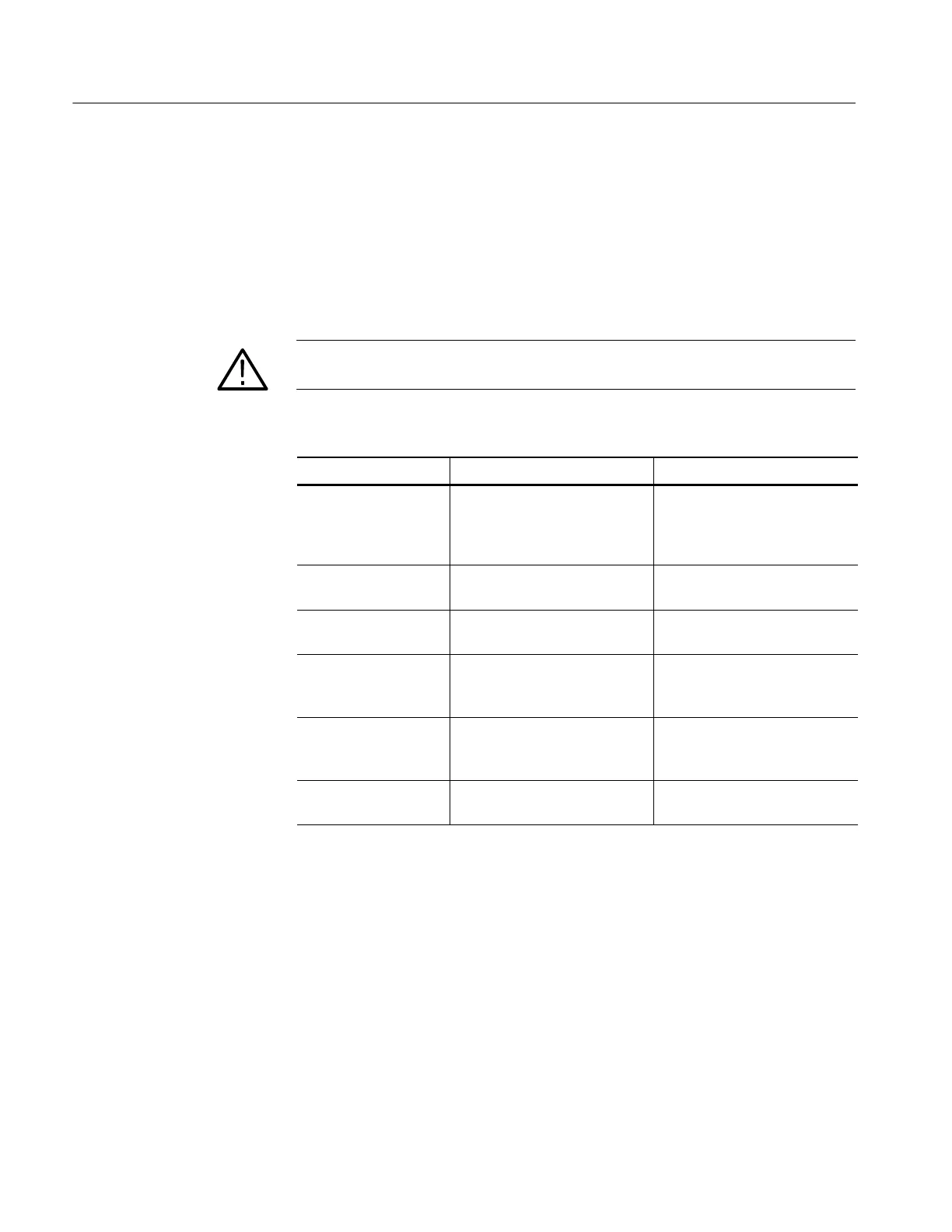
Use Table 6--2 as a guide to inspect the internal portions of the oscilloscope for
damage and wear. Repair any defects immediately.
If any circuit board is repaired or replaced, check Table 6--2 to see if it is
necessary to adjust the oscilloscope.
CAUTION. To prevent damage from electrical arcing, ensure that circuit boards
and components are dry before applying power to the oscilloscope.
Table 6--2: Internal inspection check list
Item Inspect for Repair action
Circuit boards Loose, broken, or corroded solder
connections. Burned circuit
boards. Burned, broken, or
cracked circuit-run plating.
Remove and replace damaged
circuit board.
Resistors Burned, cracked, broken, blis-
tered condition.
Remove and replace damaged
circuit board.
Solder connections Cold solder or rosin joints. Resolder joint and clean with
isopropyl alcohol.
Capacitors Damaged or leaking cases.
Corroded solder on leads or
terminals.
Remove and replace damaged
circuit board.
Wiring and cables Loose plugs or connectors.
Burned, broken, or frayed wiring.
Firmly seat connectors. Repair or
replace modules with defective
wires or cables.
Chassis Dents, deformations, and dam-
aged hardware.
Straighten, repair, or replace
defective hardware.
Cleaning Procedure, Interior. To clean the oscilloscope interior, perform the
following steps:
1. Blow off dust with dry, low-pressure, deionized air (approximately 9 psi).
2. Remove any remaining dust with a lint-free cloth dampened in isopropyl
alcohol (75% solution) and then wipe with a lint-free cloth dampened with
warm deionized water. A cotton-tipped applicator is useful for cleaning in
narrow spaces and on circuit boards.
Interior Inspection
 Loading...

