Maintenance
6-- 14
TDS1000B and TDS2000B Series Oscilloscope Service Manual
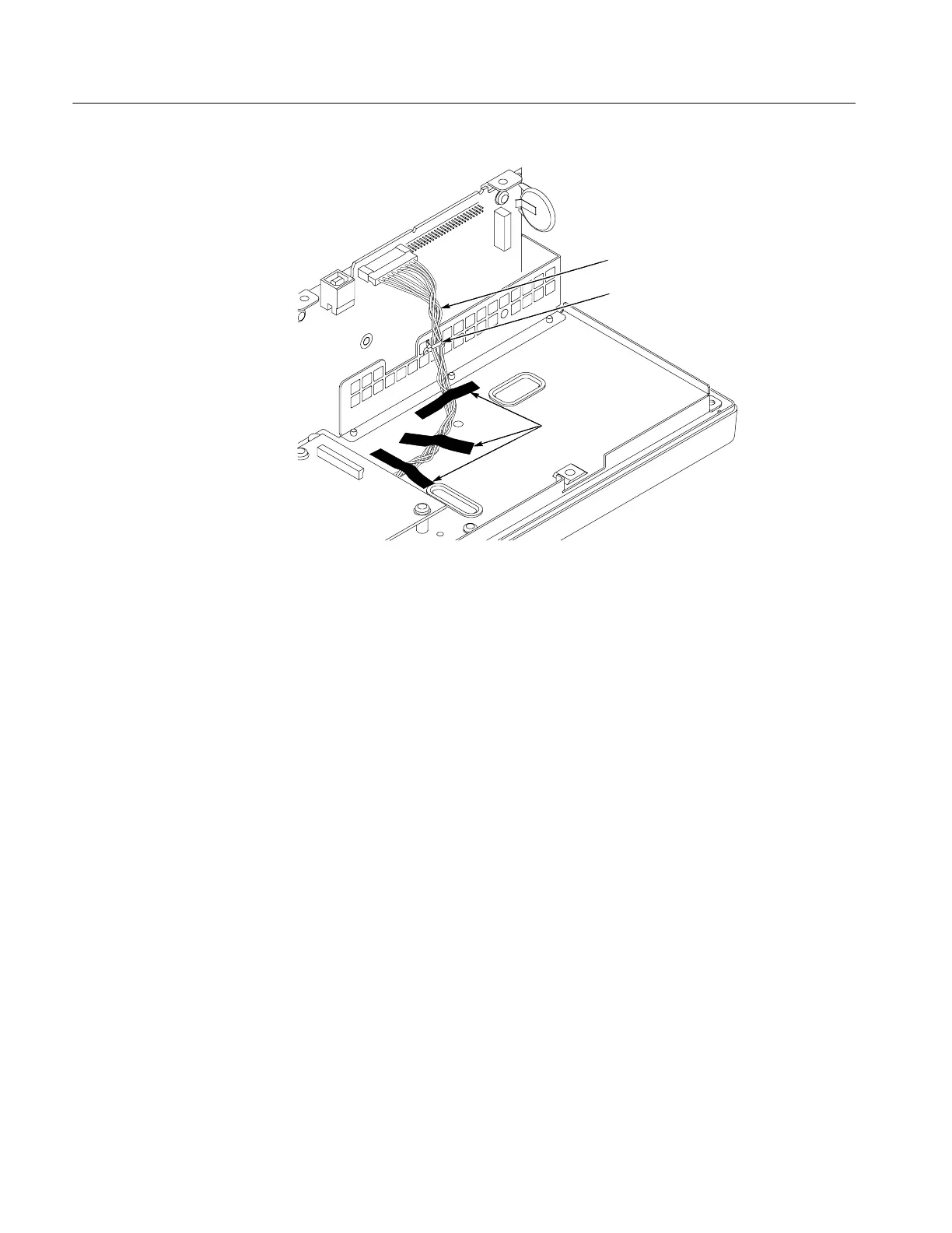
Tape the cable
to the chassis
Twist the
display cable
Addacabletie
Figure 6--3: Securing the display cable to the chassis
8. Install the four screws to attach the display module to the internal assembly.
You will need a torque-limiting Torx T-15 screwdriver and pliers for this
procedure.
Removal. To remove the front-panel cable, refer to Figure 8--3 and follow these
steps:
1. Remove the front-panel knobs, power button, and rear case using the
procedures on page 6--9.
2. Remove the internal assembly using the procedure on page 6--12.
3. Remove the five screws attaching the front panel board to the chassis.
4. Untwist the cable tie to release the front-panel cable.
5. Disconnect the front-panel cable at J202 on the main board by pulling
straight up from the connector.
6. Disconnect the front-panel cable at J1 on the front-panel module.
Front-Panel Cable
 Loading...

