Maintenance
6-14
TDS3000B Series Service Manual
3. Install the feet into the front case if you removed them in a previous step.
4. Place the disk drive into its cavity in the front panel chassis. The flex cable
should align with connector J800 on the main board. Be careful not to bend
or break the metal grounding fingers that are in the front panel disk drive
cavity.
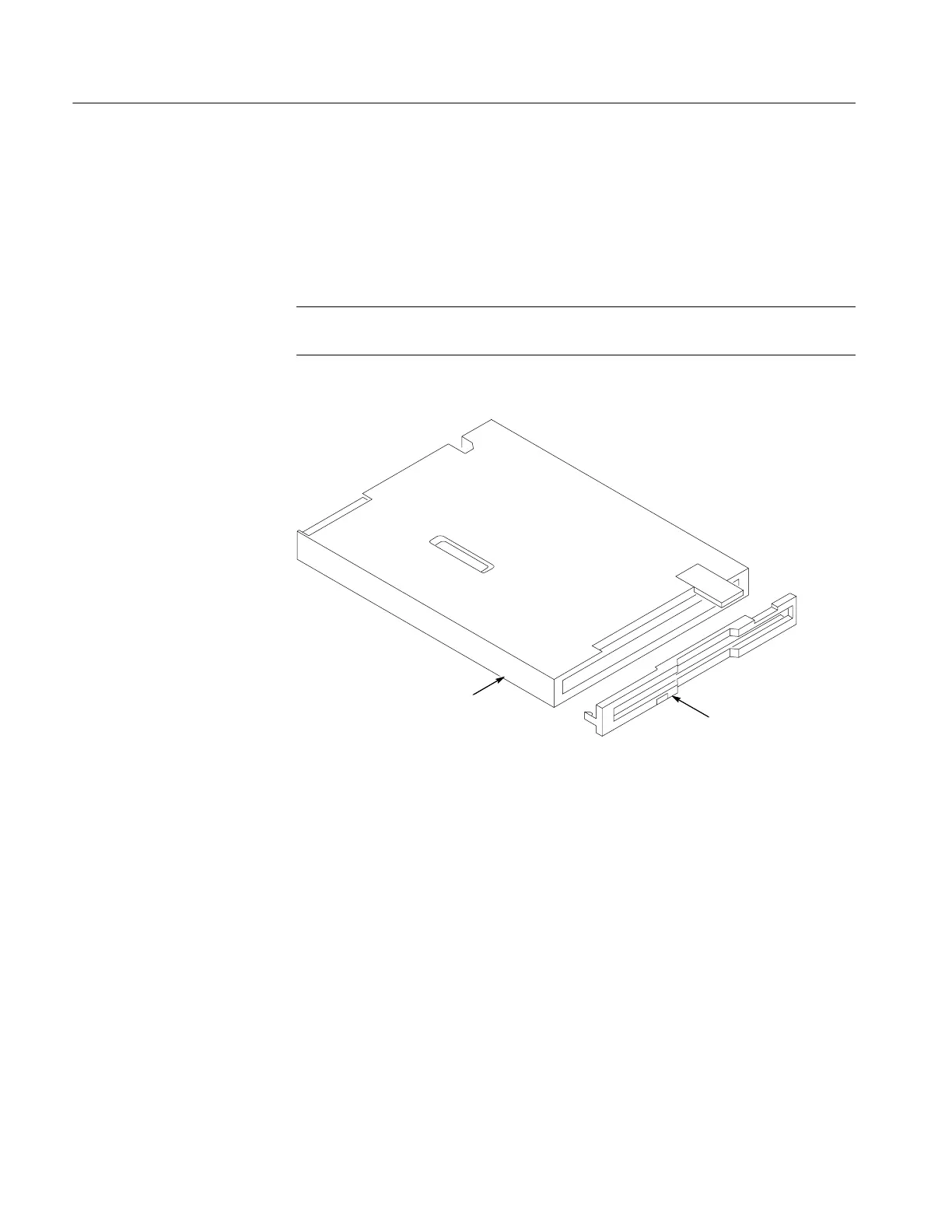
NOTE. If you are installing a new disk drive, remove the plastic bezel from the
new disk drive and discard the bezel. See Figure 6--6.
Disk drive
Bezel
Figure 6- 6: Removing the bezel from a new disk drive
5. C arefully open main board connector J800, insert the disk drive flex
connector, and then close the connector. See Figure 6--5.
6. Place the rear case over the oscilloscope chassis and lower it. Be sure that the
disk drive i s captured i nside the case and does not slip from its correct
position. The rear case should fit over and capture the feet.
7. Press the rear case downward so that it is seated completely.
8. Install the screw below the parallel port connector.
 Loading...

