Maintenance
6-30
TDS3000B Series Service Manual
7. Insert the front chassis assembly into the oscilloscope. Insert t he right end of
the front chassis slightly ahead of the l eft end to clear a slight interference at
the right end of the chassis.
8. R oute the front-panel cable through the notch located on the bottom edge of
the front chassis. S ee Figure 6 --17.
9. Use the Torx® T-10 screwdriver to insert the two screws that secure the front
chassis to the front case.
You will need a
1
@
8
inch flat-bladed screwdriver to remove the display module
inverter board.
Removal. Use this procedure to remove the display module inverter board and
back light tubes.
1. P l ace the display module face down on a soft surface (such as an anti-static
mat), with the bottom facing you.
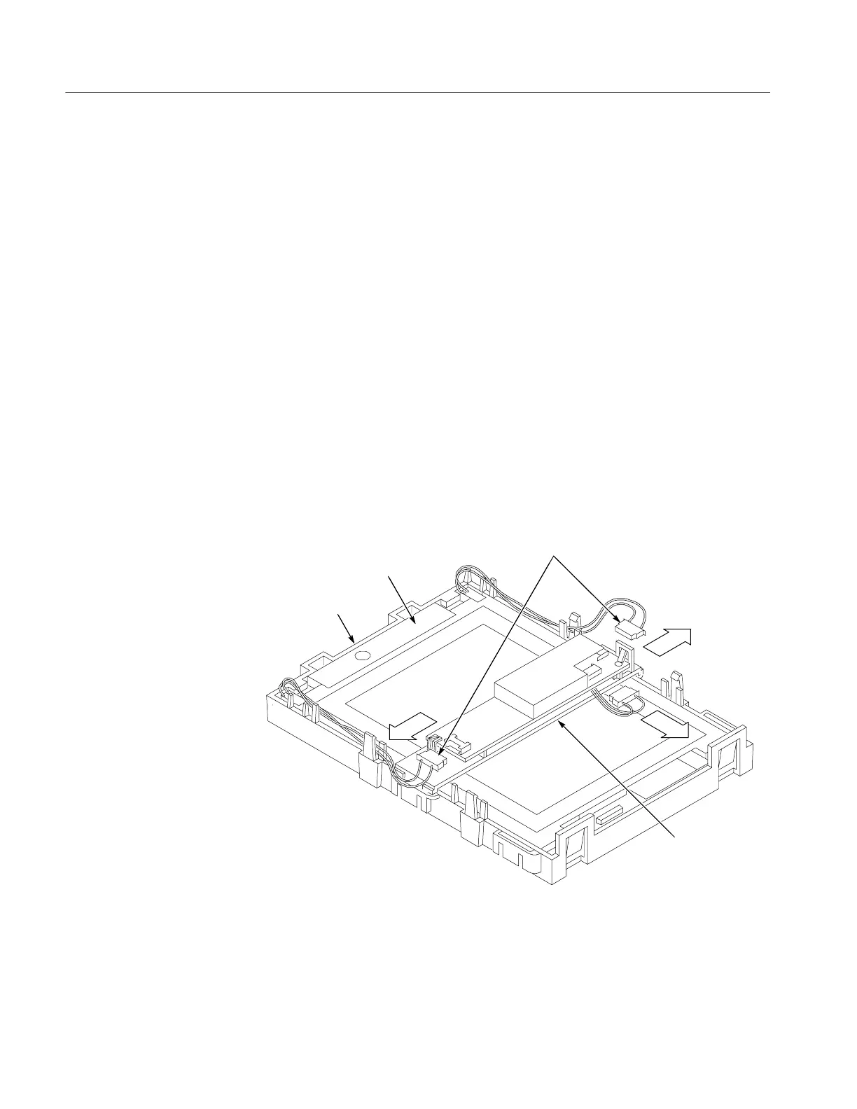
2. Disconnect the back light cables from the inverter board. See Figure 6--18.
Back light cables
Display module
Display chassis
Inverter board
assembly
Figure 6- 18: Disconnect back light cables
Display Inverter Board
and Back light Tubes
 Loading...

