Basic operation
This section includes information about the probe input limits, using the probe controls, and procedures for connecting the
probe to your circuit.
Probe input model
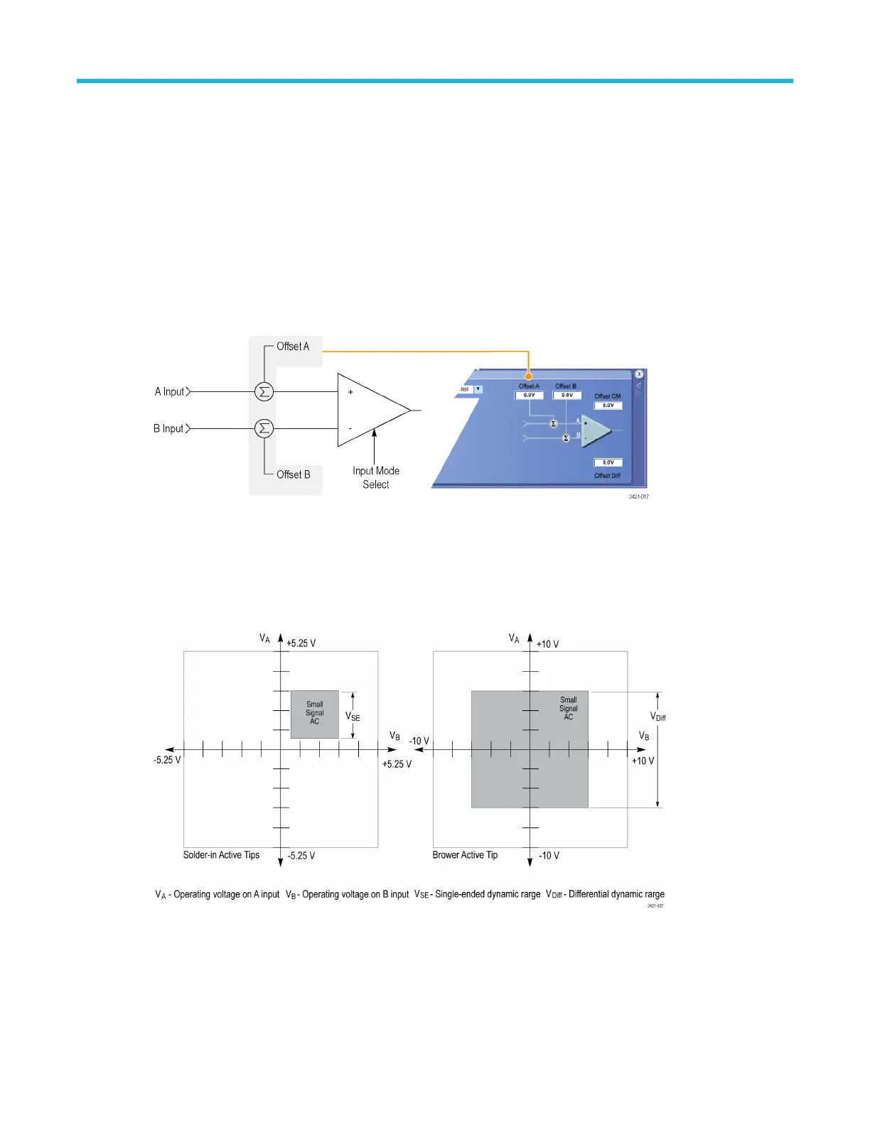
A simplified input model of the probe is shown below to illustrate the probe offset voltage controls. The probe has two
symmetrical signal inputs, the A input and the B input, which you can display independently or in combination by selecting
the appropriate probe input mode. The probe also has independent offset voltage controls for the probe A and B input
signals.
Figure 1: Simplified probe input model
Offset voltage
The offset voltage adjusts the probe input dynamic range within the larger probe input operating range, as shown in the
following figure. The probe input dynamic range is the region where an input signal is within the linear operating region of
the probe. The probe A and B offset voltages are set and stored as common settings for all four input modes.
Figure 2: Input dynamic range for solder-in tips and browser
Using the offset voltages
The offset voltage nulls out the DC bias component of an input signal, allowing the (generally smaller) AC component of the
signal to be displayed. The offset voltage shifts the center of the dynamic range, allowing more resolution for inputs not
Basic operation
P7700 Series TriMode™ Probes 17

 Loading...


