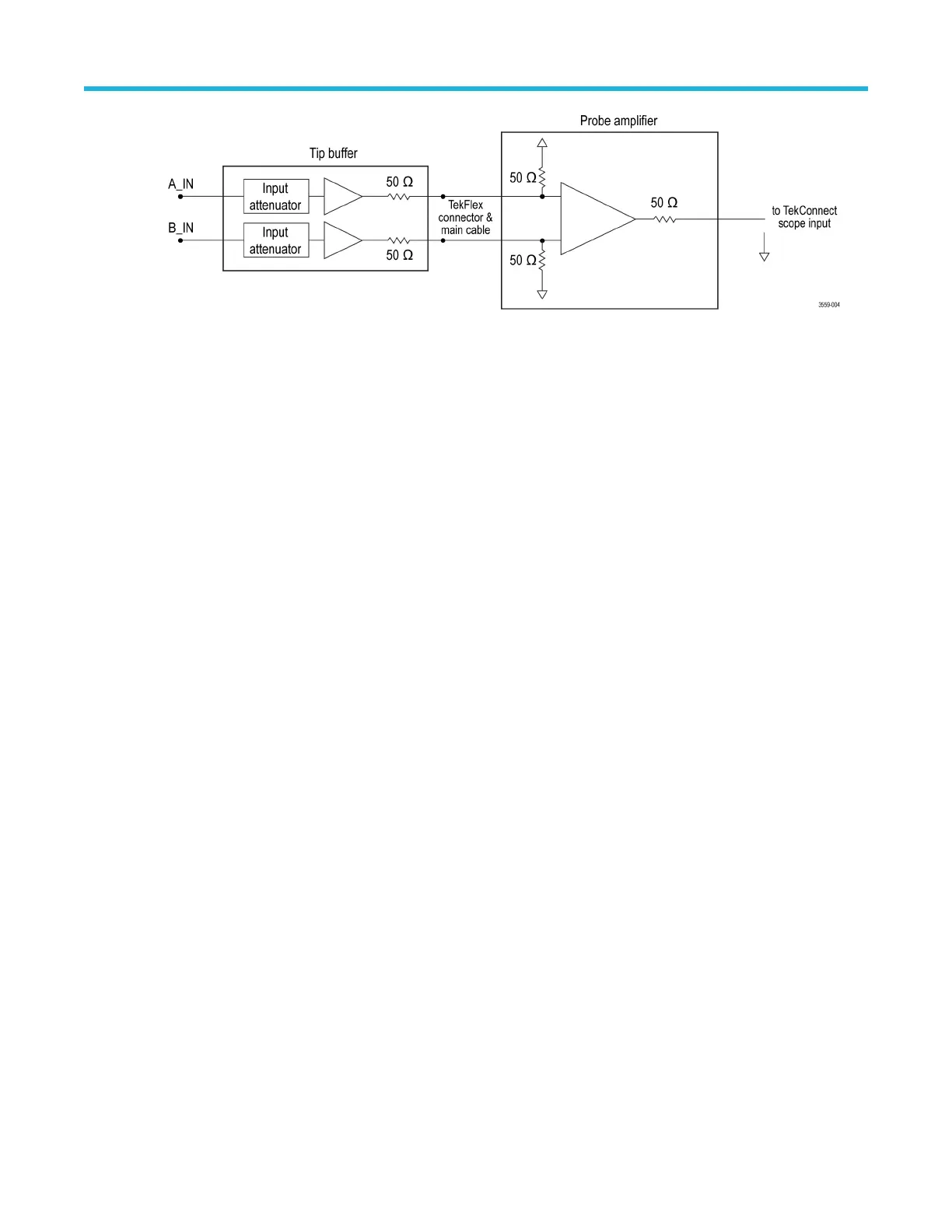
Figure 4: Simplified probe architecture diagram
The probe tip dual input buffer also provides high DC resistance input attenuators, which are carefully designed to minimize
high frequency loading on the input signals. The attenuation factor of the buffer input attenuators depends on the probe tip
type. Using a different attenuation factor allows you to trade-off dynamic range for noise performance.
The probe comp box contains the main probe amplifier, as shown above. This main probe amplifier has a differential input
termination network that receives the buffered A and B input signals from the active probe tip. The main probe amplifier has
a TriMode input configuration for switching between differential, single-ended, and common-mode measurements. The
probe main amplifier has a wide gain range with variable gain control for calibrated gain performance and to optimize noise
performance. The probe main amplifier is also capable of driving the 50 ohm signal path of the probe TekConnect
FlexChannel interface with the host oscilloscope.
Solder-in tip connection wire length
There are four via locations for soldering wire connections between the probe tip and the measurement DUT.
The via connections include the probe tip A and B inputs for a differential signal and two ground connections for best
performance and flexibility in connecting to a close DUT ground. In general, the probe tip soldered wire connection length
should be kept as short as possible. In addition, the probe tip A and B input wires should be matched in length for best
Differential mode measurement performance.
The Differential input mode does not require a ground reference wire connection, since the differential measurement
process provides its own virtual ground. The single-ended input modes, which include A-GND mode, B-GND mode, and
Common mode, all require at least one ground wire connection. However, if there is room for another connection and a
circuit ground near the probe tip, hooking up a ground connection is recommended. This might help avoid a situation where
a large potential on the ground plane of the DUT causes the test signal to drift outside of the linear range of the input
amplifier of the probe. Ideally, it is a good idea to hook up the differential inputs and the ground to avoid clipping of the
signal in the probe amplifier.
The measurement performance of the single-ended input modes is affected by the length of the ground wire connection,
with high frequency performance degradation increasing with increased ground wire length. The solder-in probe tip
performance is specified using a test fixture built with a probe tip having a signal wire length of 10 mils (.25 mm) and a
ground wire length of 66 mils (1.7 mm).
Please see the Specifications Technical Reference manual available for download at the Tektronix website for more detailed
specifications on wire length as it affects tip performance.
Please see the Probing tips for high performance design and measurement application note available for download at the
Tektronix website for more detailed specifications on wire length as it affects tip performance. (See HTTPS://
WWW.TEK.COM/DOCUMENT/APPLICATION-NOTE/PROBING-TIPS-HIGH-PERFORMANCE-DESIGN-AND-
MEASUREMENT.)
Basic operation
P7700 Series TriMode™ Probes 24

 Loading...


