signals. If the probe tip B input is connected to a DUT ground, the resulting Differential Input mode measurement (A – 0 V)
results in a display of the single-ended A input signal response.
When making differential signal measurements, the P77BRWSR P77BRWSR Offset Voltage control is normally set to the
Common-mode (CM) Tracking mode. With CM tracking mode active, the A and B input signals are monitored and the
Offset A and Offset B settings are both adjusted to match the DC common-mode voltage of the A and B input signals [(A +
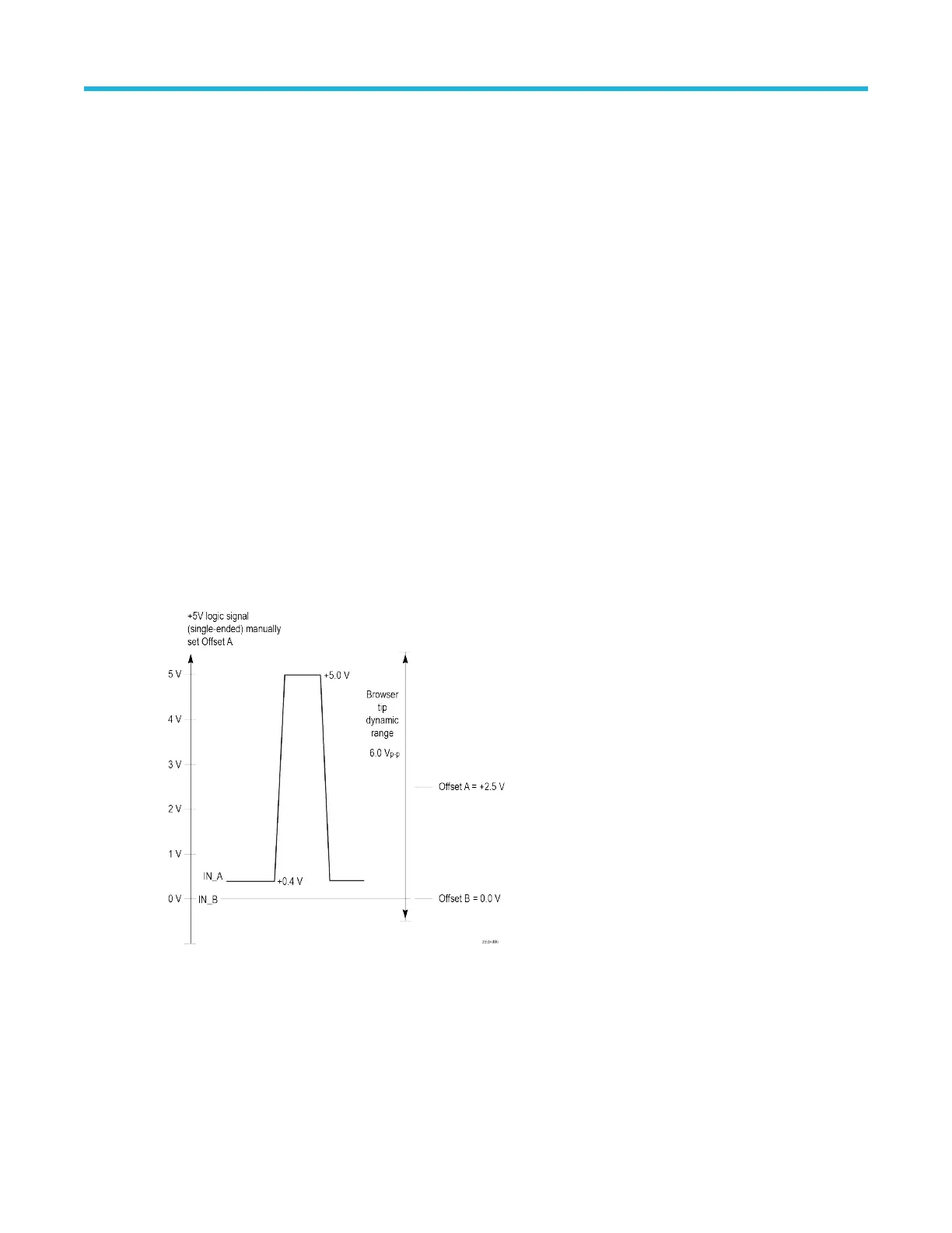
B)/2]. When making single-ended measurements in Differential Input mode with a browser tip, the offset voltage control
should be set manually, so tracking mode should be shut off. The Offset A voltage should be set manually to the center of
the A signal voltage swing. For a +5 V CMOS logic signal; for example, the Offset A voltage should be set to +2.5 V. The A
signal input voltage should then range from +5 V to 0 V, which is within the 6 V
p-p
dynamic range of the Browser tip as long
as the offset voltage is set near the center of its expected voltage swing. The Offset B voltage should also be set manually
to 0 V. This Offset B voltage setting is not only at the center of the dynamic range for a grounded B input signal, it also
causes the differential offset voltage to equal the Offset A voltage. This is true because the differential offset voltage equals
the difference between the Offset A voltage setting and the Offset B voltage setting. The differential offset voltage is used by
the oscilloscope as the displayed offset voltage in Differential Input mode. The differential Offset voltage should be set
manually to the center of the signal voltage swing. The common mode offset should be set to 1/4 of the signal swing. For a
+5 V CMOS logic signal; for example, the differential offset voltage should be set to +2.5 V and the common mode offset
should be set +1.25V. The A signal input voltage should then range from +5 V to 0 V, which is within the 6 Vp-p dynamic
range of the Browser tip as long as the offset voltage is set near the center of its expected voltage swing. These offset
settings maximize the dynamic range of single ended measurements for the differential browser.
With the tip configured for a single-ended measurement in Differential Input mode, the displayed signal voltage should
match the A input signal response and the displayed offset voltage should match the Offset A setting. Since the host
oscilloscope uses both the displayed signal voltage and displayed offset voltage in calculating its set of available
oscilloscope automated measurements, it is important that both the Differential Input mode signal voltage and offset voltage
are configured properly as shown in the following figure. See Figure 6: Proper configuration of the Differential Input mode
signal and offset voltage on page 26.
Figure 6: Proper configuration of the Differential Input mode signal and offset voltage
The configuration process described in this section will maximize the available dynamic range of the P77BRWSR
P77BRWSR tip when making single-ended measurements.
Basic operation
P7700 Series TriMode™ Probes 26

 Loading...


