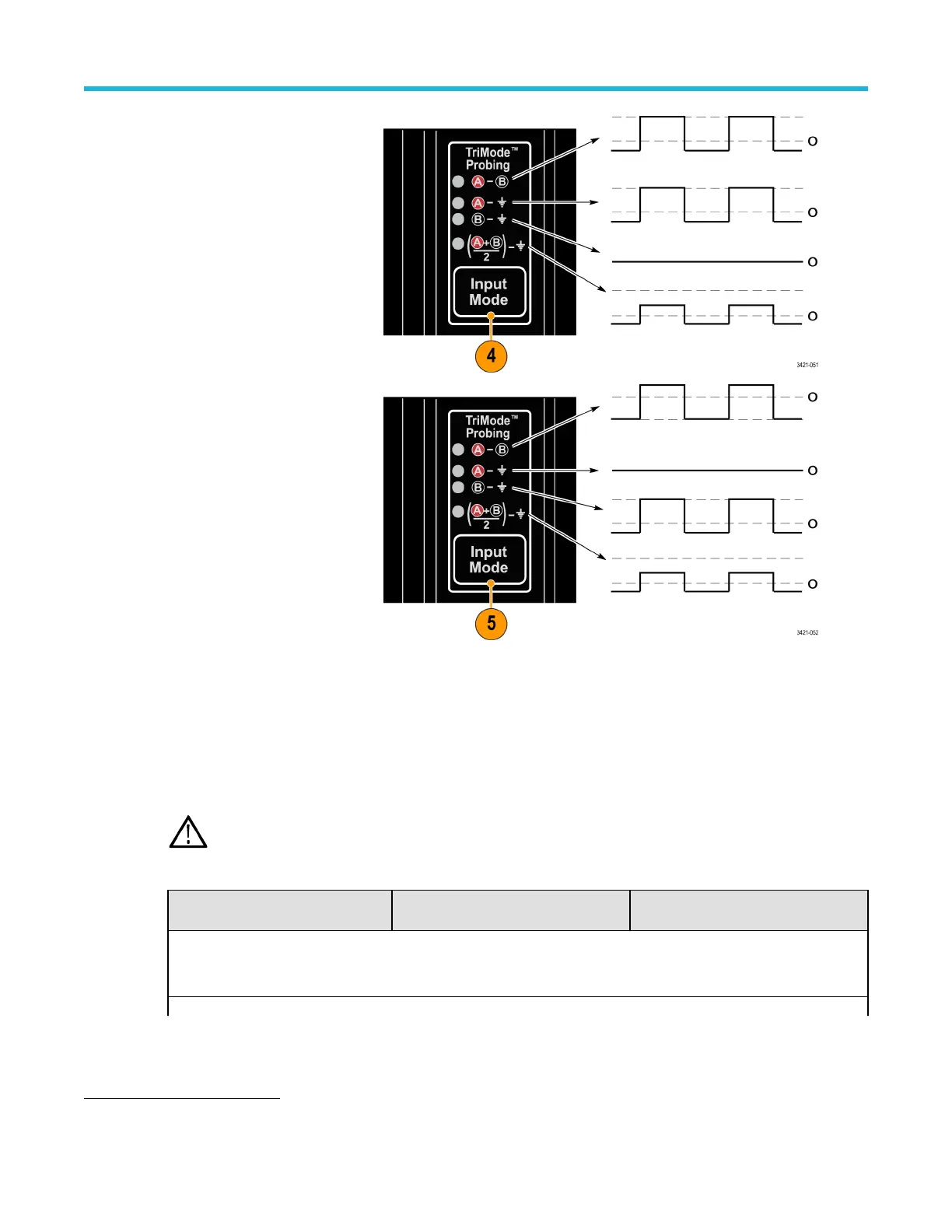
Cycle the Input Mode button
through the remaining selections
and compare the displayed
waveforms to the waveform
measured in the setup steps.
Change the FAST EDGE????
cable connection from the
Deskew Fixture A input to the B
input. If using the P77CSMAMM
adapter, disconnect the A SMA
cable from the FAST EDGE????
output and connect the SMA B
cable. Repeat the displayed
waveform checks. The
measurements should be
different as follows:
TriMode probe DC compensation
To maximize the amplitude accuracy of measurements made with a P7700 TDP7700 series probe, you should run a probe
compensation routine on each channel that you use. The probe compensation operation minimizes measurement errors by
optimizing the DC gain and offset of the probe. Individual compensation constants are stored for all TriMode settings, on
each probe, on each channel.
CAUTION: To avoid ESD damage to the probe, always use an antistatic wrist strap (provided with your probe), and
work at a static-approved workstation when you handle the probe.
Table 4: Required equipment, DC compensation
Item description Performance requirement
Recommended example
7
Oscilloscope TekConnect Interface
TekVPI Interface
Tektronix MSO/DPO70000C/70000DX
Tektronix MSO6 Series
Table continued…
7
Nine-digit part numbers (xxx-xxxx-xx) are Tektronix part numbers
Functional check and calibration
P7700 Series TriMode™ Probes 12

 Loading...


