Collimating
Lenses
Grating
Wavepass
Filter
Slit
Lamp
Lamp
DMD Board
Microcontroller Board
DLP Controller Board
Detector Board
Detector
Sample
Window
Focusing
Lenses
Collection
Lenses
Illumination
Module
What is the DLP NIRscan Nano EVM?
www.ti.com
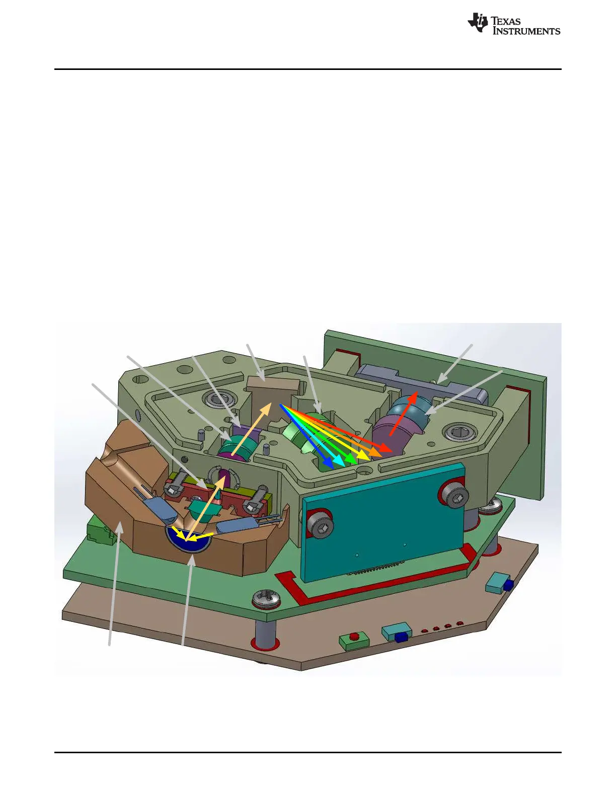
through the input slit. The slit size is chosen to balance wavelength resolution with SNR of the
spectrometer. This spectrometer uses a 25-μm wide by 1.69-mm tall slit. The light that passes through the
slit is collimated by the first set of lenses, passes through an 885-nm long wavepass filter, and then strikes
a reflective grating. This grating, in combination with the focusing lens, disperses the light into its
constituent wavelengths. The focusing lenses form an image of the slit at the DLP2010NIR DMD. Different
wavelengths of this slit image are spread horizontally across the DLP2010NIR DMD. The optical system
images 900-nm wavelengths to one end of the DMD and 1700-nm to the other end, with all other
wavelengths dispersed in between. When specific DMD columns are selected as on, or tilted to the +17°
position, the energy reflected by the selected columns is directed through the collection optics to the single
pixel InGaAs detector. All other DMD columns selected as off, or tilted to the –17° position, diverts the
unselected wavelengths away from the detector optical path so as not to interfere with the selected
wavelength measurement.
The DLP NIRscan Nano reflectance module operates by illuminating the sample under test at an angle so
that specular reflections are not collected, while gathering and focusing diffuse reflections to the slit. The
illuminating lamps are designated as lens-end lamps because the front end of the glass bulb is formed into
a lens that directs more light from the filament to the sample test region. The collection lens gathers
collimated light from a 2.5-mm diameter region at the sample window. The size of the collection region
was matched to the nominal illumination spot size created by the lens-end lamps. This requires that the
sample be placed directly against the sapphire window, where the two angled light source paths intersect
the collection vision cone of the lens. If the sample is shifted farther away from the window, the sample
may not receive enough illumination for the system to perform an accurate scan.
Figure 1-2. DLP NIRscan Nano Optical Engine
The optical engine footprint drives the size of the DLP NIRscan Nano EVM. The NIRscan Nano EVM
measures approximately 62-mm long, 58-mm wide, and 36-mm tall as shown in Figure 1-3.
10
DLP NIRscan Nano Overview DLPU030B–June 2015–Revised July 2015
Submit Documentation Feedback
Copyright © 2015, Texas Instruments Incorporated

 Loading...


