FUNCTION CHARACTERISTICS
127
setting the I2>Curve parameter (DEFINITE,IEC/BSA,IEC/BSB,IEC/BSC,ANSI/IEEMI,
ANSI/IEEVI,ANSI/IEEEI,I2t,EM) available inside the Set \ Profile A (or B) \ Negative sequen-
ce overcurrent - 46LT \ I2> Element \ Setpoints menu.
The trip of I2> element may be inhibited by the start of the second element (I2>>) by set-
ting ON the Disable I2> by start I2>> (I2>disbyI2>>) parameter available inside the
Set \ Profile A (or B) \ Negative sequence overcurrent-46LT \ I2>> Element \ Setpoints menu.
An adjustable reset time delay is provided for every threshold (t
2
>
RES
, t
2
>>
RES
)..
Breaker failure (BF)
Each thresholds (I2>, I2>>) can be associated to BF (H) and BF (L) protection by activating the relative
parameter in the matrices “Selection of function tripping for BF (H)” or “Selection of function tripping
for BF (L)” in relevant BF menus
2
:
• Set \ Profile A (or B) \ Breaker failure - BF side H
• Set \ Profile A (or B) \ Breaker failure - BF side L
Second harmonic restraint
For all elements, a block from the second harmonic restraint may be set by setting ON the I>2n-
dh-REST,I>>2ndh-REST parameters inside the Set \ Profile A (or B) \ Negative sequence over-
current - 46LT \ I2> Element (I2>> Element) \ Setpoints menus.
Cold load pickup
If the CLP function (Cold Load Pick-up) is enabled for element blocking, the selected threshold may
be blocked for an adjustable time interval, starting from the circuit breaker closure.
This operating mode may be select by setting
ON-Elementblockingthe I2CLP>Modeand/or
I2CLP>>Mode parameters.
If the CLP function (Cold Load Pick-up) is enabled for threshold change, the selected threshold may
be changed for an adjustable time interval, starting from the circuit breaker closure.
This operating mode may be select by setting
ON-Change setting the I2CLP> Mode and/or
I2CLP>>Mode parameters, whereas the operating thresholds within the CLP may be adjusted
inside the Set \ Profile A (or B) \ Negative sequence overcurrent - 46LT \ I2> Element,(I2>> Ele-
ment) \ Definite time (Inverse time) menus.
For both operating modes the CLP Activation time parameters (
t2CLP>,t2CLP>>) may be adju-
sted inside the Set \ Profile A (or B) \ Negative sequence overcurrent - 46LT \ I2> Element (I2>>
Element) \ Setpoints menus.
For both thresholds the following block criteria are available:
Logical block (Block1)
If the I2>BLK1 and/or I2>>BLK1 enabling parameters are set to ON and a binary input is desi-
gned for logical block (Block1), the concerning element is blocked off whenever the given input is
active.
3
The enabling parameters are available inside the Set \ Profile A (or B) \ Negative sequence
overcurrent - 46LT \ I2> Element (I2>> Elemen) \ Setpoints menus, while the Block1 function must be
assigned to the selected binary input inside the Set \ Board 1(2) inputs \ Binary input IN1-1...(IN1-x)
menus.
Selective block (Block2)
All along the protective elements the selective block may be set.
The logic selectivity function may be performed by means any combination of the following I/O:
• One committed pilot wire input (BLIN1).
• One or more binary inputs designed for input selective block.
• One committed pilot wire output (BLOUT1).
• One or more output relays designed for output selective block.
Only when the committed pilot wire are used the continuity check of the pilot wire link is active.
Use of committed pilot wire input BLIN1:
• The protection is blocked off according the selectivity block criteria when the input BLIN1 is active.
The information about phase or phase+earth block may be select programming the ModeBLIN1
parameter inside the Set \ Profile A (or B) \ Selective block-BLOCK2 \ Selective block IN menus.
Note 2 The common settings concerning the Breaker failure protection are adjustable inside the Breaker Failure - BF menu.
Note 3 The exhaustive treatment of the logical block (Block 1) function may be found in the “Logic Block” paragraph inside CONTROL AND MONITOR-
ING section
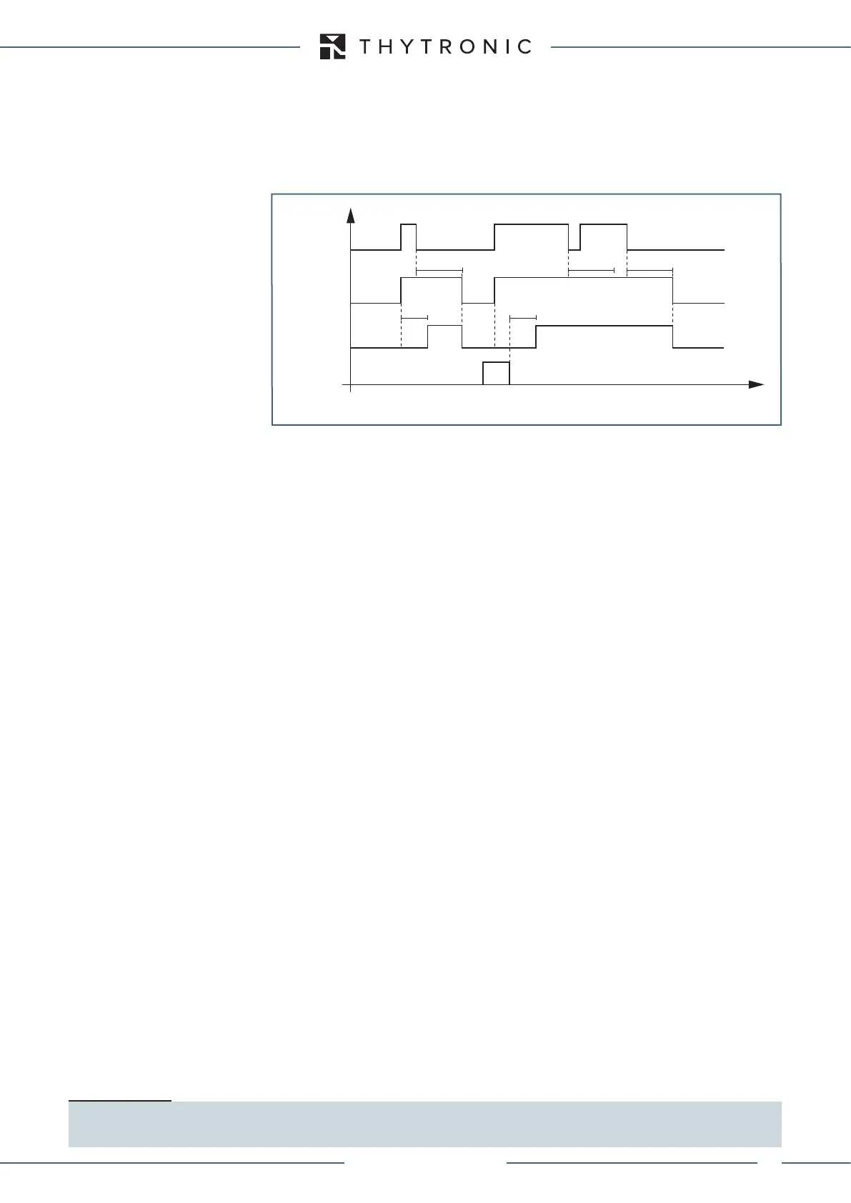
Timers-F46.ai
I2> Start
I2> Trip
t
2
> t
2
>
RESET
INPUT
t
2
>
RES
t
2
>
RES
t
2
>
RES
t
I2> element timers - 46LT (first element)
XMR-D EQUIPMENT MANUAL
Ed. 2.9 - 02/2021
 Loading...
