FUNCTION CHARACTERISTICS
171
Setting notes ((50+27)
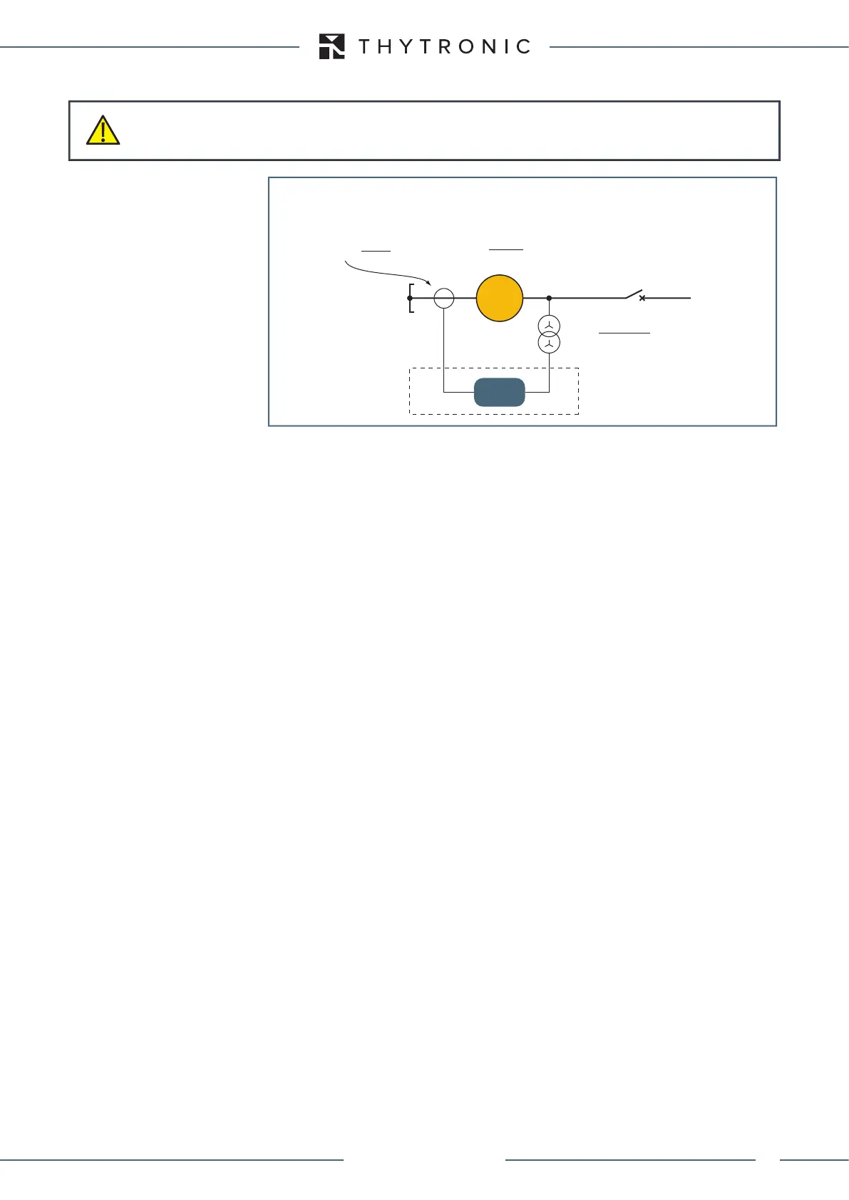
Target: Inadvertent energization protection for a generator directly with following settings:
• Voltage threshold (machine stopped): 80% of the rated phase voltage of the generator.
• Current threshold (machine stopped):10% of the rated phase current of the generator.
• Enabling delay (operate time):5 s.
• Reset delat to enable: 0.5 s.
The relay nominal frequency must be set to 50 Hz: f
n
= 50 Hz.
The relay nominal current (I
n
) must be set to the CTs secondary nominal current (dip-switch and sw
setting): I
n
=5 A.
The nominal voltage (U
n
) of the line inputs (phase to phase voltage) must be set to the grid nominal
voltage value divided by the VT ratio:
U
n
=(Grid nominal voltage in volt) / VTs ratio (K
VT
) = 6000/[(6000/√3)/(100/√3)] = 6000/60 =100 V
From the nominal voltage setting, the relay rated phase voltage is calculated by the relay:
(En=Un/√3=57.8 V)
In this example the VTs are located on the generator side of the machine circuit breaker, so the
Generatorsideparameter for VT positionmust be set inside the Profile A (B) \ Inadvertent ener-
gization \ 1st pickup Element \ Setpoints menu.
The voltage restraint threshold setting must be defined according the general formula:
U
UE
<= voltage restraint threshold (primary volt) /(E
n
·K
TV
)
So:
U
UE
<=(80%U
ng
/√3)/[57.8·(6000/√3)/(100/√3)]=0.8·6000/√3/(57.8·60)=0.80 p.u. E
n
The amperometric threshold setting must be defined according one of the the following general
formula:
I
UE
>= Required phase current (primary ampere)/(I
n
·K
TA
)
So:
I
UE
>=(10%I
ng
)/(5·500/5)=0.1·481.44/(5·100)=0.10 p.u. I
n
The operating time and the reset time delay settings are:
t
UE
>=5.0 s
t
UE-RES
=0.5 s
CAUTION
Settings must be established on the basis of a coordination study.
Numerical values inside examples have educational purpose only; they don’t be used, in no way,
for actual applications.
Appl-50+27.ai
50+27
f
n
= 50 Hz
3x
S
ng
= 5 MVA
U
ng
= 6 kV
G
XMR-D
K
VT
= = 60
6000/√3 V
100/√3 V
I
ng
=
= 481.13 A
S
ng
√3 U
ng
K
CT
= = 100
500 A
5 A
XMR-D EQUIPMENT MANUAL
Ed. 2.9 - 02/2021
 Loading...
