76
FUNCTION CHARACTERISTICS
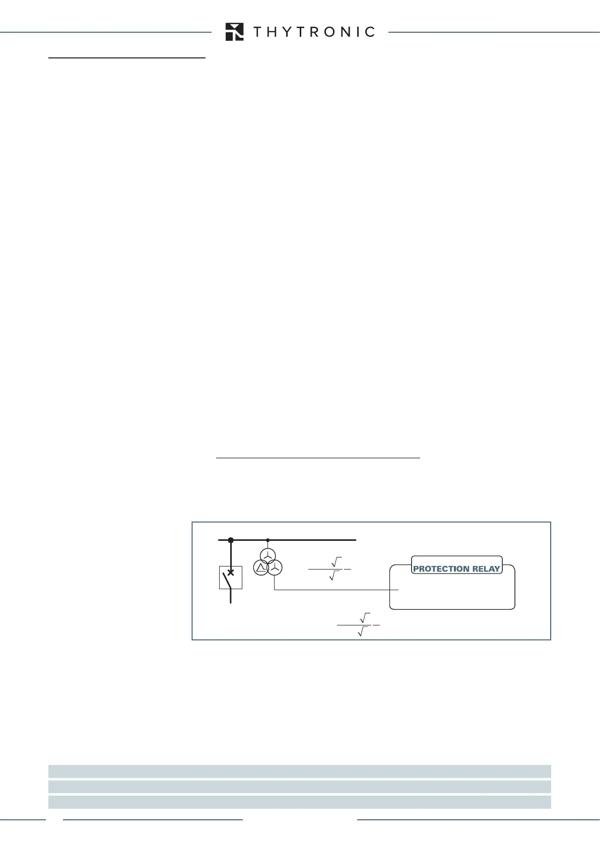
4.4 PROTECTIVE ELEMENTS
— Rated values
Inside the Base menu the following parameters can be set:
• Relay reference name
• The the reference for the settings of relay rated currents (phase and residual)
• Primary nominal values, employed for to return measures in the primary values
• Measurements reading mode (primary or relative values)
• Reset delay for Cold Load Pickup
[1]
Information for settings:
• Relay reference name.
Alphanumeric mnemonic string (max 16 characters) useful for identification of protected plant.
• Relay nominal frequency f
n
This nominal value must be set same as the frequency of the grid.
Example: grid frequency f
n
= 50 Hz
Relay nominal frequency f
n
= 50 Hz
• Relay phase rated current for side H and side L I
nH
, I
nL
This rated value must be set to 1 A or 5 A
[2]
, same as the secondary CTs rated current.
• Rated primary phase current chosen as reference (I
nref
)
CT’s primary current chosen by relay for amplitude compensation.
• Rated primary phase current chosen as reference (RefSide)
Choice of the reference side for the phase compensation currents
• Number of sides for differential protection (NumSides)
Setting the number of sides on which the differential protection operates (fixed to 2)
• Current matching type (MatchType)
Setting the current compensation type (INT-internal, EXT-external CTs)
• Protected object (ProtObj)
Setting the type of protecting object (fixed to TRANSF)
• Relay residual current - side 1 and side 2 (I
En1
and I
En2
)
This rated values must be set by means dip-switch to 1 A or 5 A
[3]
, same as the secondary residual
CT rated current.
• Relay phase-to-phase voltage U
n
Two reference voltage are available: U
R
=100 V and U
R
=400V
For the first instance the U
n
relay nominal voltage must be set to the phase-to-phase voltage of the
secondary VTs voltages at grid nominal voltage.
The U
n
value must calculated as:
If VTs with primary rated voltage is equal to the grid voltage divided by √3, the following streamlined
calculus may be used:
U
n
= VTs secondary rated voltage [V] x √3
Example 1
The relay rated voltage may be set to:
U
n
= U
ng
/K
VT
= 6900 / 100 = 69 V
Note 1 Parameter available at level 1 only
Nota 2 Per rendere attiva la modifica della regolazione, dopo il comando “Fine tarature“ è necessario RIAVVIARE IL DISPOSITIVO
Nota 3 Per rendere attiva la modifica della regolazione, dopo il comando “Fine tarature“ è necessario RIAVVIARE IL DISPOSITIVO
Voltage transformer ratio K
VT
ng
where the VTs are included [V]
U
n
=
Es1-Un.ai
K
VT
=
/
/
V
V
10000
3
100 3
= 100
/
/
V
V
10000
3
100 3
= 100
Grid rated voltage U
ng
= 6.9 kV
VTs ratio K
VT
=
U
ng
= 6.9 kV
U
n
52
XMR-x
XMR-D EQUIPMENT MANUAL
Ed. 2.9 - 02/2021
 Loading...
