176
FUNCTION CHARACTERISTICS
The second overcurrent element can be programmed with definite or inverse time characteri-
stic by setting the I> Time characteristic (I(H)>>Curve) parameter (
DEFINITE, I2t) available
inside the Set \ Profile A (or B) \ Phase overcurrent-50/51 side H \ I(H)> Element (I(H)>> Element,
I(H)>>> Element) \ Setpoints menu.
The trip of I(H)> element may be inhibited by the start of the second and/or third element (I(H)>>,
I(H)>>>) by setting ON the Disable I(H)> by start I(H)>>, Disable I(H)>> by start I(H)>>> (I(H)>di-
sbyI(H)>>,I(H)>disbyI(H)>>>) parameters available inside the Set \ Profile A (or B) \ Phase
overcurrent-50/51 side H \ I(H)> Element (I(H)>> Element, I(H)>>> Element) \ Setpoints menus.
Similarly the trip of the I(H)>> element may be inhibited by start of the third element (I(H)>>>) by
setting ON the Disable I(H)>> by start I(H)>>> (I(H)>>disbyI(H)>>>) parameter available
inside the Set \ Profile A (or B) \ Phase overcurrent-50/51 side H \ I(H)> Element (I(H)>> Element,
I(H)>>> Element) \ Setpoints menu.
All the named parameters can be set separately for Profile A and Profile B (Set \ Profile A (or B) \
Phase overcurrent-50/51 side H \ I(H)> Element (I(H)>> Element, I(H)>>> Element) \ Setpoints menus).
An adjustable reset time delay is provided for every threshold (t
(H)
>
RES
, t
(H)
>>
RES
, t
(H)
>>>
RES
).
Breaker failure (BF)
Each thresholds (I>, I>>, I>>>) can be associated to BF (H) and BF (L) protection by activating the
relative parameter in the matrices “Selection of function tripping for BF (H)” or “Selection of function
tripping for BF (L)” in relevant BF menus
[1]
:
• Set \ Profile A (or B) \ Breaker failure - BF side H
• Set \ Profile A (or B) \ Breaker failure - BF side L
Second harmonic restraint
For all overcurrent elements, a block from the second harmonic restraint may be set by setting ON
the
I>2ndh-REST, I>>2ndh-REST, I>>>2ndh-REST parameters inside the Set \ Profile A
(or B) \ Phase overcurrent-50/51 side H \ I(H)> Element (I(H)>> Element, I(H)>>> Element) \ Setpoints
menus.
Cold load pickup
If the CLP function (Cold Load Pick-up) is enabled for element blocking, the selected threshold may
be blocked for an adjustable time interval, starting from the circuit breaker closure.
This operating mode may be select by setting
ON-Elementblockingthe I(H)CLP>Mode,I(H)
CLP>>Modeand/or I(H)CLP>>>Mode parameters.
If the CLP function (Cold Load Pick-up) is enabled for threshold change, the selected threshold may
be changed for an adjustable time interval, starting from the circuit breaker closure.
This operating mode may be select by setting
ON-Change settingthe I(H)CLP> Mode,I(H)
CLP>> Mode and/or I(H)CLP>>> Mode parameters, whereas the operating thresholds wi-
thin the CLP may be adjusted inside the Set \ Profile A (or B) \ Phase overcurrent-50/51 side H \
I(H)> Element (I(H)>> Element, I(H)>>> Element) \ Definite time (Inverse time) menus.
For both operating modes the CLP Activation time parameters (
tCLP>,tCLP>>,tCLP>>>) may
be adjusted inside the Set \ Profile A (or B) \ Phase overcurrent-50/51 side H \ I(H)> Element (I(H)>>
Element, I(H)>>> Element) \ Setpoints menus.
For every of the three thresholds the following block criteria are available:
Logical block (Block1)
If the I(H)>BLK1,I(H)>>BLK1and/orI(H)>>>BLK1 enabling parameters are set to ON and
a binary input is designed for logical block (Block1), the concerning element is blocked off whenever
the given input is active.
[2]
The enabling parameters are available inside the Set \ Profile A (or B) \
Phase overcurrent-50/51 side H \ I(H)> Element (I(H)>> Element, I(H)>>> Element) \ Setpoints menus,
while the Block1 function must be assigned to the selected binary input inside the Set \ Board1(2)
inputs \ Binary input IN1-1...INx-x menus.
Note 1 The common settings concerning the Breaker failure protection are adjustable inside the Breaker Failure - BF menu.
Note 2 The exhaustive treatment of the logical block (Block 1) function may be found in the “Logic Block” paragraph inside CONTROL AND MONITOR-
ING section
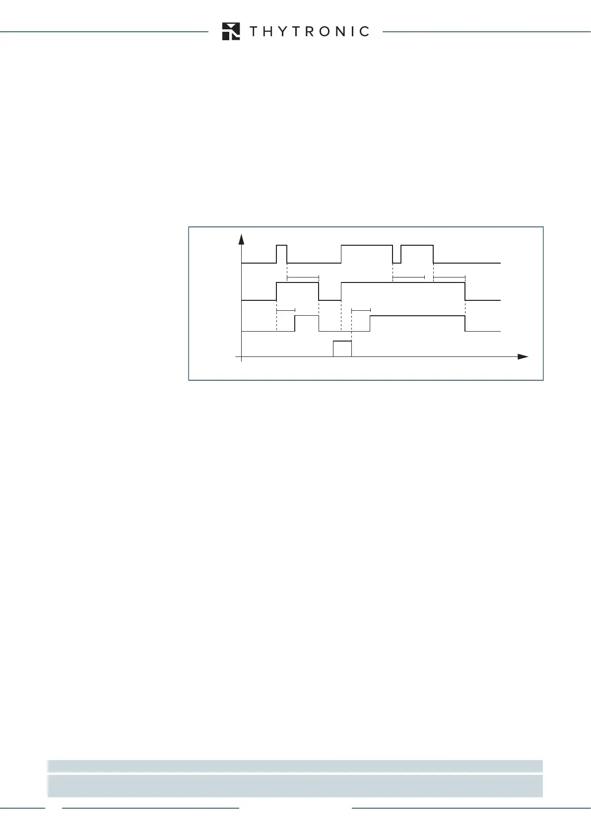
I> element phase overcurrent timers - 50/51 side H
Timers-F50-51.ai
I(H)> Start
I(H)> Trip
RESET
INPUT
t
(H)
>
RES
t
(H)
>
RES
t
(H)
>
RES
t
(H)
> t
(H)
>
t
XMR-D EQUIPMENT MANUAL
Ed. 2.9 - 02/2021
 Loading...
