24
PTT Unit
4st 9.9/15/20 2009
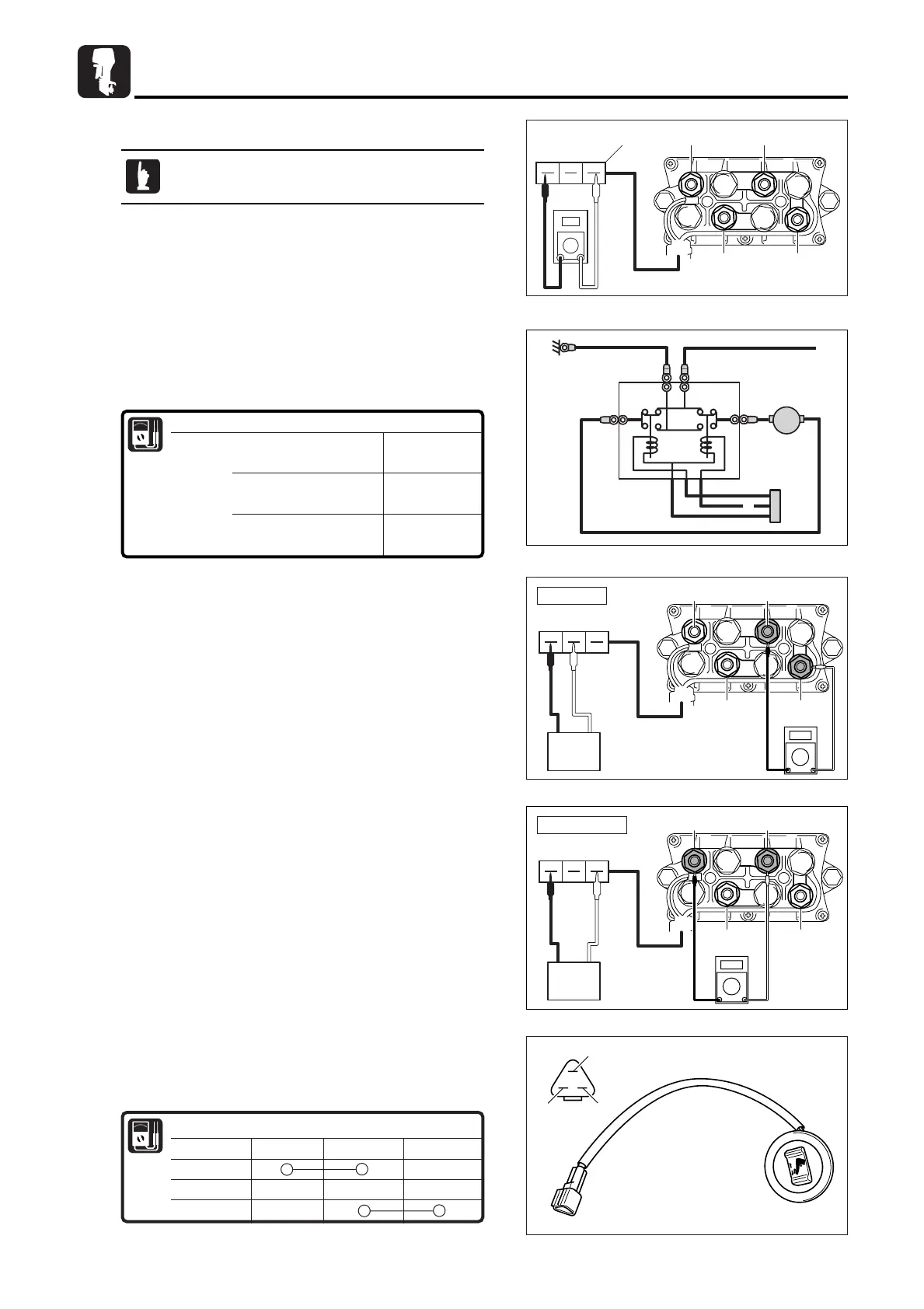
5)Inspection of PTT Relay
1. Disconnect positive and negative cables from battery.
2. Remove PTT lead wire socket a from coupler.
3. Check PTT relay wires in accordance with the following
table.
Replace if out of specification.
Inspection of DOWN side relay
6. As shown in the figure, connect green terminal (G) in the
coupler to battery positive terminal and black terminal (B) to
negative terminal, and then, connect circuit tester leads to
PTT relay terminals 2 and 3.
7. Check electrical conductivity between terminals 2 and 3.
Replace relay if non-conductive.
-+
LGB
2
G
3
(+)R
1
L
4
(-)B
2
G
3
(+)R
1
L
4
(-)B
Down circuit
-+
This test can be made without removing parts.
Conductivity of PTT relay
Coupler
{
Blue (L) - Black (B)
Conductive
Green (G) - Black (B)
Terminal 1 - Terminal 4 (
-
)
Conductive
Terminal 2 - Terminal 4 (
-
)
Terminal 1 - Terminal 3 (+)
Non-conductive
Terminal 2 - Terminal 3 (+)
-+
LGB
2
G
3
(+)R
1
L
4
(-)B
2
G
3
(+)R
1
L
4
(-)B
-+
Up circuit
Inspection of UP side relay
4. As shown in the figure, connect blue terminal (L) in the
coupler to battery positive terminal and black terminal (B) to
negative terminal, and then, connect circuit tester leads to
PTT relay terminals 1 and 3.
5. Check electrical conductivity between terminals 1 and 3.
Replace relay if non-conductive.
6)Inspection of PTT Switch
1. Check electrical conductivity of PTT switch. Replace if out of
specification.
LGB
-
+
2
G
3
(+)R
1
L
4
(-)B
2
G
a
3
(+)R
1
L
4
(-)B
Lead Wires
Switch Position Sky Blue (Sb)
Red (R) Pink (P)
UP (Tilt Up)
Free
DOWN (Tilt Down)
E_MFS15-20C_sup_body_090330.qxd 09.4.2 11:10 AM ページ 24
 Loading...