14
Description UseQty.
Parts catalog
Certificate of compliance
1
1
Operator video 1 View before operating the machine.
Operator’s manual
Engine operator’s manual
2
1
Read before operating the machine.
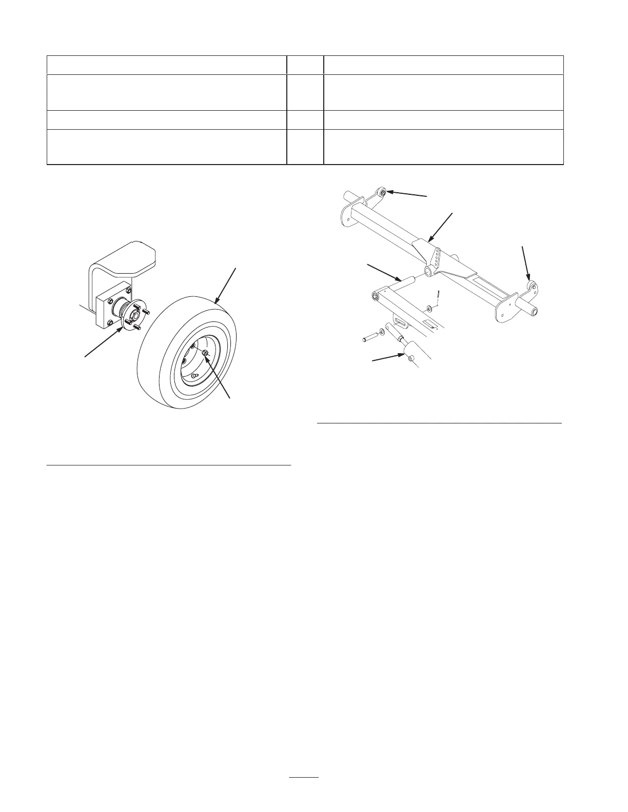
Installing the Rear Wheel
1. Mount the wheel assembly onto the rear wheel hub
(Fig. 1).
1
2
3
Figure 1
1. Wheel assembly
2. Rear wheel hub
3. Lug nut
2. Install the lug nuts (Fig. 1) and tighten them to 45–65
ft.-lb. (3–5 N⋅m).
Adjusting the Rear Carrier
Frame Height
1. Slide the rear carrier frame onto the rear lift arm pivot
rod (Fig. 2). Do not install the carrier frame to the
cutting unit at this time.
2. Raise the lift arms and carrier frame fully.
3. Press down on one end of the carrier frame until the up
stop on the opposite end contacts the underside of the
foot step (Fig. 2). The distance between the up stop and
the underside of the foot step, on the end pressed down,
should be approximately 1/4 in. (6 mm). If the distance
is not 1/4 in. (6 mm), an adjustment to the lift cylinder
is required. If the distance is correct, remove the carrier
frame and proceed with the setup instructions.
1
3
3
2
4
Figure 2
1. Rear carrier frame
2. Pivot rod
3. Up stop
4. Lift cylinder
4. If an adjustment to the lift cylinder is required, proceed
as follows:
A. Remove the clevis pin securing the rod end of the
lift cylinder to the lift arm (Fig. 2).
B. Loosen the hex nut securing the clevis to the
cylinder rod.
C. Rotate the clevis end in or out until 1/4 in. (6 mm)
clearance is attained. Check the adjustment and
repeat steps 2–3 as required.
D. Tighten the hex nut and connect the cylinder rod end
to the lift arm (Fig. 2).
Mounting the Carrier Frames to
the Cutting Units
1. Remove the cutting units from the cartons. Adjust them
per the Cutting Unit Operator’s Manual.
2. Position a carrier frame onto each cutting unit, aligning
the mounting holes with the mounting links (Fig. 3).
 Loading...