25
Operation
Note: Determine the left and right sides of the machine
from the normal operating position.
Controls
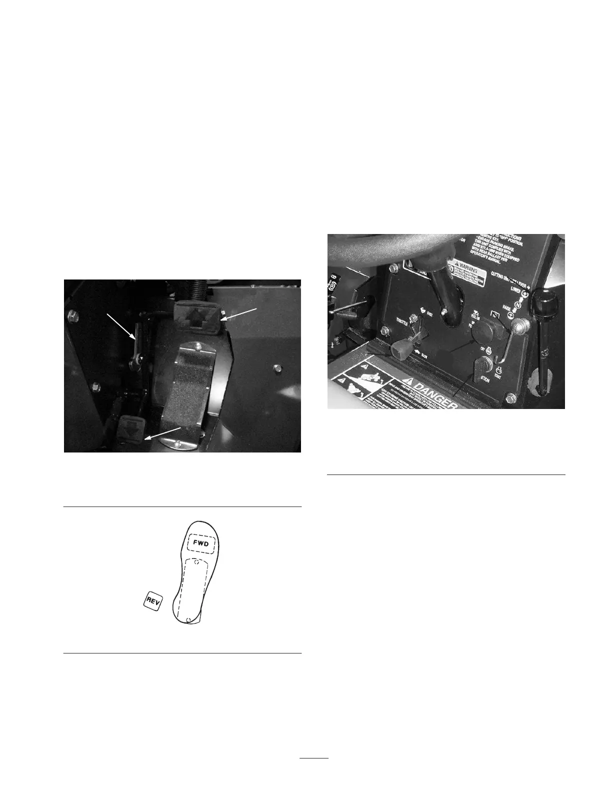
Traction and Stopping Pedal
The traction pedal (Fig. 26) has three functions: to make
the machine move forward, to move it backward, and to
stop the machine. Using the heel and toe of the right foot,
depress the top of the pedal to move forward and the
bottom of the pedal to move backward or to assist in
stopping when moving forward (Fig. 27). Also, allow the
pedal to move or move it to the neutral position to stop the
machine. For operator comfort, do not the rest heel of your
foot on reverse when operating forward.
1
2
3
Figure 26
1. Traction pedal
2. Speed selector
3. Pedal stop
Figure 27
Speed Selector
The speed selector is a cam lever at the side of the traction
pedal (Fig. 26) that can be rotated to maintain desired
speed.
The reverse pedal stop (under the pedal) (Fig. 26) is set at
the factory to provide 3 MPH maximum speed in reverse.
Starter Switch
The starter switch (Fig. 28), used to start, stop, and preheat
the engine, has three positions: OFF, ON, and START.
Rotate the key clockwise to ON position and hold until
glow plug light goes out. Then rotate the key clockwise
(START position) to engage the starter motor. Release the
key when the engine starts. The key will move
automatically to the ON/RUN position. To shut the engine
off, rotate the key counterclockwise to the OFF position.
Remove the key from the switch to prevent accidental
starting.
2
1
3
4
5
Figure 28
1. Starter switch
2. Throttle
3. Cutting unit drive switch
4. Cutting unit lift lever
5. Cutting unit lift lever lock
Throttle
Moving the throttle (Fig. 28) upward increases the engine
speed and downward decreases the engine speed.
Cutting Unit Lift Lever
The lift lever (Fig. 28) has three positions: LOWER,
RAISE, and NEUTRAL. To lower the cutting units to the
ground, move the lift lever forward. When lowering the
cutting units, make sure that the front hydraulic cylinder is
completely retracted before releasing the lift lever. The
cutting units will not operate unless the cylinder is
retracted. To raise the cutting units, pull the lift lever
rearward to the RAISE position.
Cutting Unit Lift Lever Lock
The cutting unit lift lever lock (Fig. 28) locks cutting units
in the raised position for transporting.
 Loading...