15
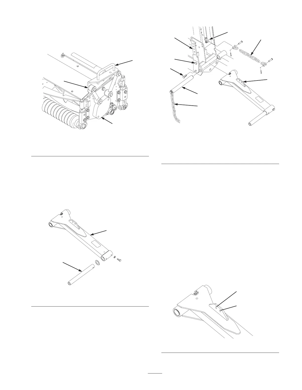
3. Secure each mounting link to the carrier frame with a
capscrew (3/8 x 2-1/4 in.), 2 flat washers, and a locknut,
as shown in Figure 3. Position a washer on each side of
the link when mounting. Torque to 31 ft.-lb. (42 N⋅m).
1
3
2
Figure 3
1. Carrier frame
2. Mounting link
3. Bearing housing cover
Installing the Front Lift Arms
1. Insert a pivot rod into the left lift arm and align the
mounting holes (Fig. 4).
2. Secure the pivot rod to the lift arm with a capscrew
(5/16 x 7/8 in.) and lock washer.
1
2
Figure 4
1. Lift arm 2. Pivot rod
3. Loosen the top capscrew securing the left
counterbalance arm to the frame (Fig. 5).
1
2
3
4
5
8
6
7
Figure 5
1. Counterbalance arm
2. Top capscrew
3. Bottom capscrew
4. Lift arm pivot pin
5. Tipper chain
6. Lift chain
7. Cylinder pin
8. Lift arm tab
4. Remove the bottom capscrew and nut securing the left
counterbalance arm to the frame (Fig. 5).
5. Rotate the counterbalance arm outward, allowing
removal of the lift arm pivot pin and tipper chain
(Fig. 5).
6. Position the lift arm between the frame members, align
the mounting holes, and install the pivot pin (Fig. 5).
Insert the pivot pin so that the counterbalance arm fits
into the slot in the pin. Do not secure the counterbalance
arm at this time.
7. Secure one end of the lift chain to the lift cylinder pin
with a clevis pin and cotter pin.
8. Secure the other end of the lift chain to the hole in the
lift arm mounting tab with clevis pins and cotter pins.
Use the appropriate hole in the lift arm as designated in
Figure 6.
9. Repeat the procedure on the right-hand lift arm.
32” Cutting Unit
(Outer Hole)
27” Cutting Unit
(Inner Hole)
Figure 6
 Loading...