Setup
Loose Parts
Use the chart below to verify that all parts have been shipped.
Step
Description
Qty.
Use
1
Handle
1
Install the handle.
Kickstand assembly
1
Spring
1
Small spacer
1
Large spacer 1
Large bolt (M8–1.25 x 100)
1
Small bolt (M8–1.25 x 030)
1
Locknut (M8 x 1.25)
2
2
Washer (M8)
2
Install the kickstand for Flex 18
Mowers Only.
3
No parts required
–
Adjust the handle.
4
Transport wheels (Optional
Transport Wheel Kit, Model 04123)
2
Install the transport wheels.
5
No parts required
–
Check the engine oil and
transmission uid levels
6
Grass basket
1
Install the grass basket.
Operator’s Manual
1
Engine Operator’s Manual
1
Parts Catalog
1
Operator Video
1
7
Certicate of compliance
1
Read the manuals and watch
the video before operating the
machine.
Note: Deter mine the left and right sides of the
mac hine from the nor mal operating position.
Step
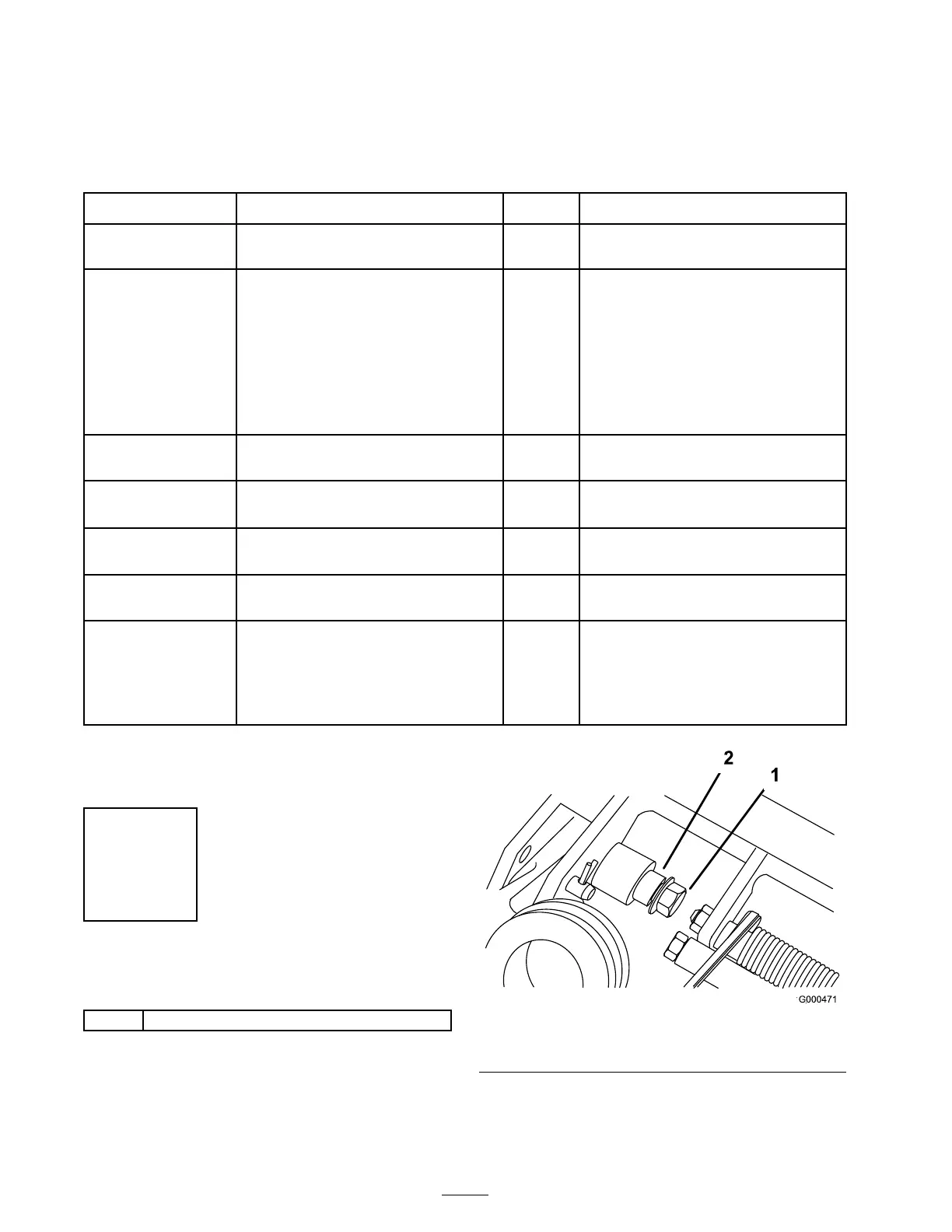
1
Installing the Handle
Parts needed for this step:
1
Handle
Procedure
1. R emo v e the flang e loc k n ut from the bolt and
pi v ot pin on eac h side of the mo w er ( Figure 4 ).
Figure 4
1. Flange lock nut
2. Pivot pin
2. Inser t the handle ends through the slots in the
handle suppor t ar ms ( Figure 5 ).
10

 Loading...


