Figure 45
1. Reel control cable
3. Tighten front cable jam n ut.
4. Chec k control operation.
Cutting Unit
Maintenance
Separating the Cutting Unit
from the Traction Unit
1. Place the mo w er on its dr ums on a lev el
surface .
2. Lo w er kic k stand. Inser t a 1/4" dia. pin or
equi v alent into frame hole abo v e kic k stand
mounting bolt ( Figure 46 ).
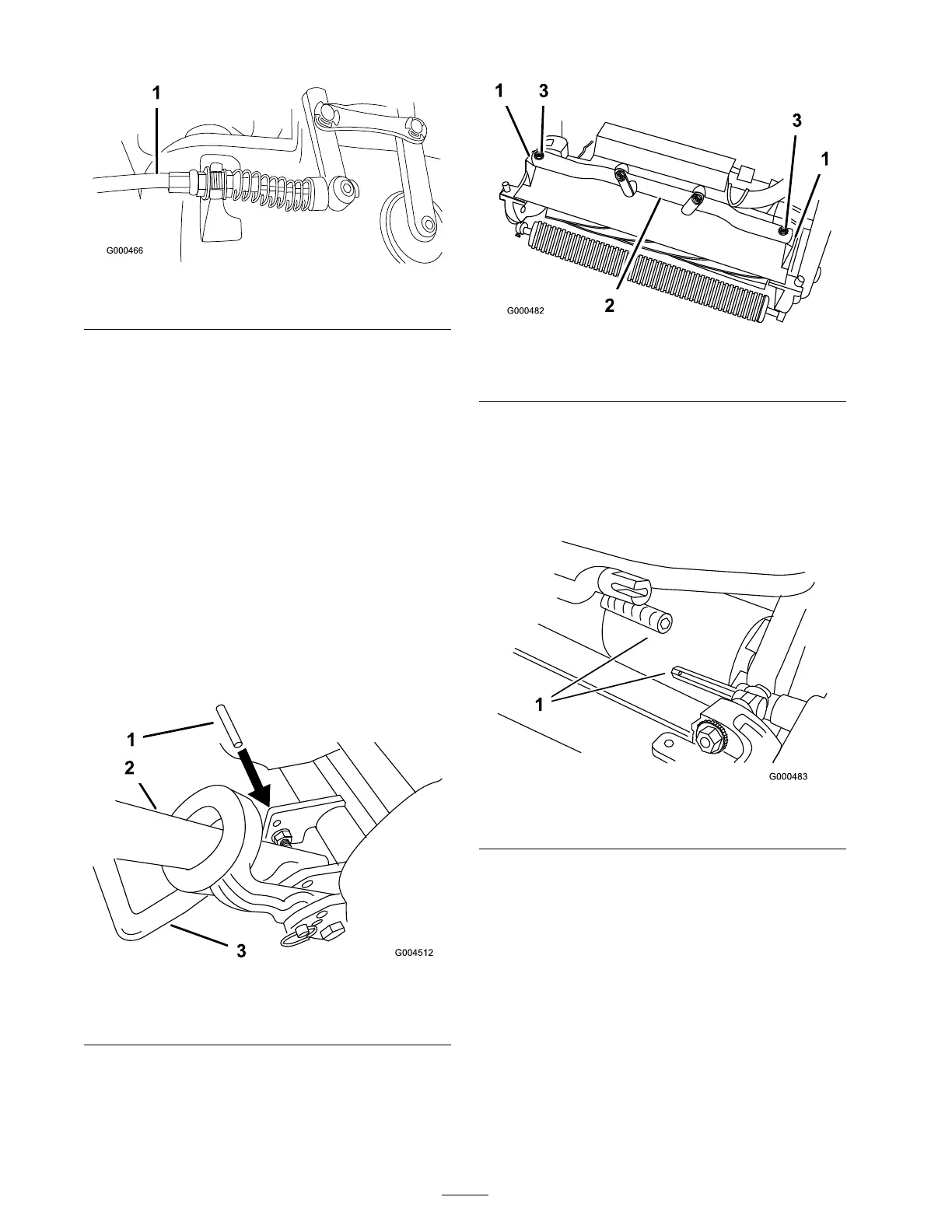
Figure 46
1. 1/4" Pin 3. Kick stand
2. Handle
3. R emo v e g rass bask et.
4. R emo v e (2) bolts securing cutting unit pi v ot
ar ms to traction unit frame tube ( Figure 47 ).
Figure 47
1. Cutting unit pivot arms
3. Bolts
2. Traction unit frame tube
5. R otate pi v ot ar ms forw ard ( Figure 47 ) and rest
traction unit on restrained kic kstand.
6. Pull cutting unit forw ard about 2 inc h
(51 mm) and then to the right to diseng ag e the
transmission coupling ( Figure 48 ).
Figure 48
1. Transmission coupling
7. R ev erse procedure to install cutting unit.
Adjusting the Rear Roller
1. Adjust the rear roller brac k ets to the lo w or
high position de pending on desired height of
cut rang e ( Figure 49 and Figure 50 ).
• P osition the spacer abo v e the side plate
mounting flang e (factor y setting) when
height of cut settings rang e from 1/16 to
1/4" (Fig . 10).
32

 Loading...


