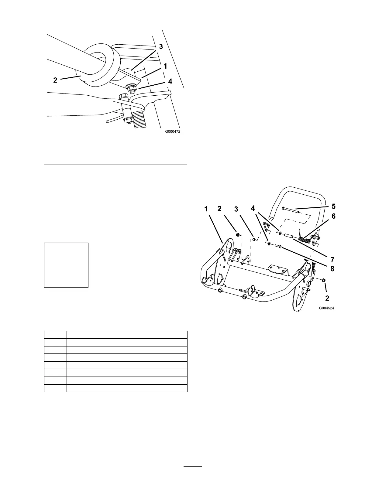
Figure 5
1. Left handle end
3. Pivot pin
2. Support arm
4. Locknut
3. Squeeze the handle ends inw ard and install
them on the ste p of the pi v ot pin ( Figure 5 ).
4. Secure the handle to the bolt and pi v ot pin
with the flang e loc k n ut ( Figure 5 ).
5. Locate cable tie loosely securing throttle
cable to wire har ness . P osition cable tie
appro ximately one inc h behind transmission
and tighten cable tie .
Step
2
Installing the Kickstand for
Flex 18 Mowers Only
Parts needed for this step:
1
Kickstand assembly
1
Spring
1
Small spacer
1 Large spacer
1
Large bolt (M8–1.25 x 100)
1
Small bolt (M8–1.25 x 030)
2
Locknut (M8 x 1.25)
2
Washer (M8)
Procedure
1. P osition the kic kstand betw een the tabs on the
rear of the frame .
2. Install a w asher (M8) onto the small bolt
(M8–1.25 x 030). Install the right side of
the kic kstand to the frame with the bolt
and w asher , the small spacer , and loc kn ut
(M8–1.25) ( Figure 6 ). Ensure the bolt is
installed from the inside of the frame as sho wn
in Figure 6 .
3. Install a w asher (M8) onto the larg e bolt
(M8–1.25 x 100).
4. Install the spacer into the spring and install the
larg e bolt (M8–1.25 x 100) into the spacer .
Important: W hen installing the spring ,
place one end of the spring under the r ear
frame ( Figur e 6 ).
5. Install the left side of the kic kstand to the
frame with the bolt and w asher , the larg e
spacer and spring, and loc kn ut (M8–1.25)
( Figure 6 ). Ensure the bolt is installed from the
inside of the frame as sho wn in Figure 6 .
Figure 6
1. Left handle end
5. Large bolt (M8–1.25 x 100)
2. Locknut (M8–1.25)
6. Spring
3. Small spacer
7. Large spacer
4. Washer (M8) 8. Ssmall bolt (M8–1.25 x
030)
6. Place a n ut r unner o v er the end of the spring
pointing to w ards the rear and mo v e the end of
the spring o v er and under the kic kstand spacer
( Figure 7 ).
11

 Loading...


