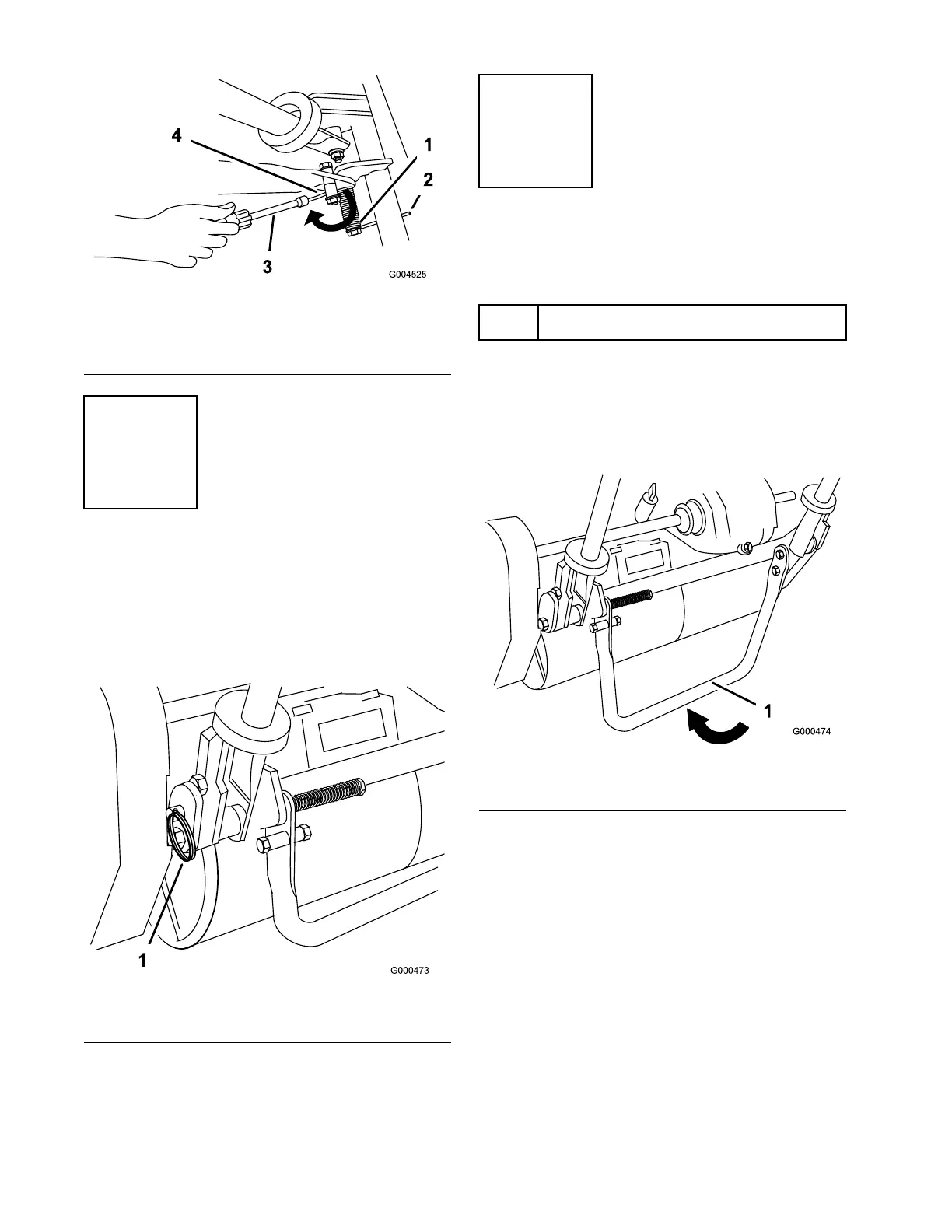
Figure 7
1. Spring
3. Nut runner
2. Spring end under the frame 4. Move the spring end under
the kickstand spacer.
Step
3
Adjusting the Handle
No Parts Required
Procedure
1. R emo v e hair pin cotters from ring pins on eac h
side of mo w er ( Figure 8 ).
Figure 8
1. Ring pins
2. W hile suppor ting handle , remo v e ring pins
from eac h side and raise or lo w er handle to
desired operating position ( Figure 8 ).
3. R einstall ring pins and hair pin cotters .
Step
4
Installing the Transport
Wheels
Parts needed for this step:
2
Transport wheels (Optional Transport Wheel
Kit, Model 04123)
Procedure
1. Push kic k stand do wn with foot and pull up
on handle suppor t until kic k stand has rotated
forw ard, o v er center ( Figure 9 ).
Figure 9
1. Kick stand
2. Press wheel loc king clip to w ard the center
of wheel and slide wheel onto hex shaft
( Figure 10 ).
12

 Loading...


