16
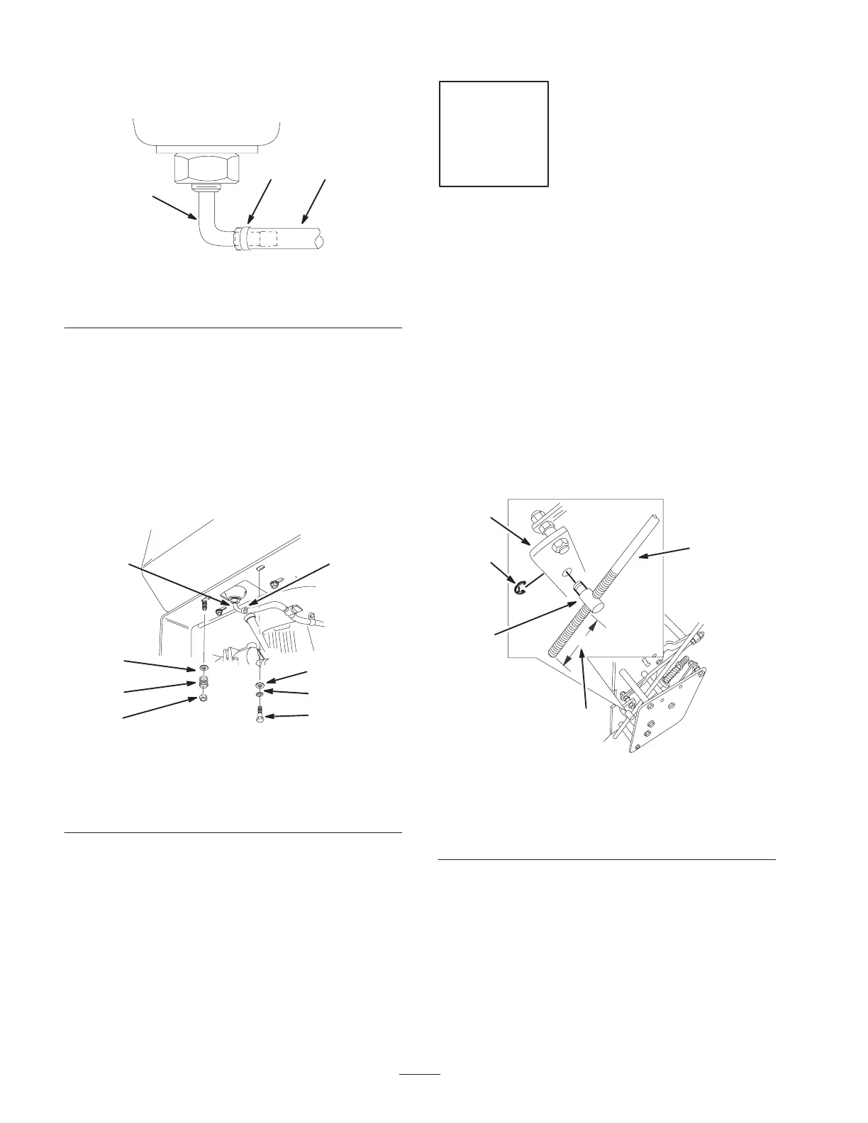
Note: Make sure the fuel line and clamp are on as shown
in Figure 6.
m–6504
2
1
3
Figure 6
1. Fuel line
2. Clamp
3. Fuel tank connection
4. Secure the right side of the fuel tank to the rear frame
(Fig. 7) with 2 bolts (5/16 x 7/8 inch), lock washers
(5/16 inch) and washers (5/16 inch) (Fig. 7).
5. Secure the left side of the fuel tank to the rear frame
(Fig. 7) with washers (5/16 inch), springs and locknuts
(5/16 inch) (Fig. 7).
Note: Tighten left side of shift lever plate until it is
completely tight and then unscrew the locknut one full
turn. This will allow the spring to work.
5
4
3
2
1
3
7
6
m–6583
Figure 7
1. Bolt, 5/8 x 7/8 inch
2. Lock washer, 5/16 inch
3. Washer, 5/16 inch
4. Spring
5. Locknut
6. Hose clamp
7. Fuel tank connection
Step
4
Installing the Control Rods
Parts needed for this step:
Qty. Part
2
E–ring
Procedure
1. For a starting point, make sure the rod fittings are
threaded approximately 2–1/2 inches (63 mm) onto the
control rods (Fig. 8).
2. Install the rod fittings into the control arms and secure
them with E–rings (Fig. 8).
1
3
2
m–6601
4
5
Figure 8
1. Control rod
2. Rod fitting
3. 2–1/2 inch (63.5 mm) from
bottom
4. E–ring
5. Control arm
3. Place the clevis pins into the control rods, drive levers
and neutral locks (Fig. 9).
 Loading...