17
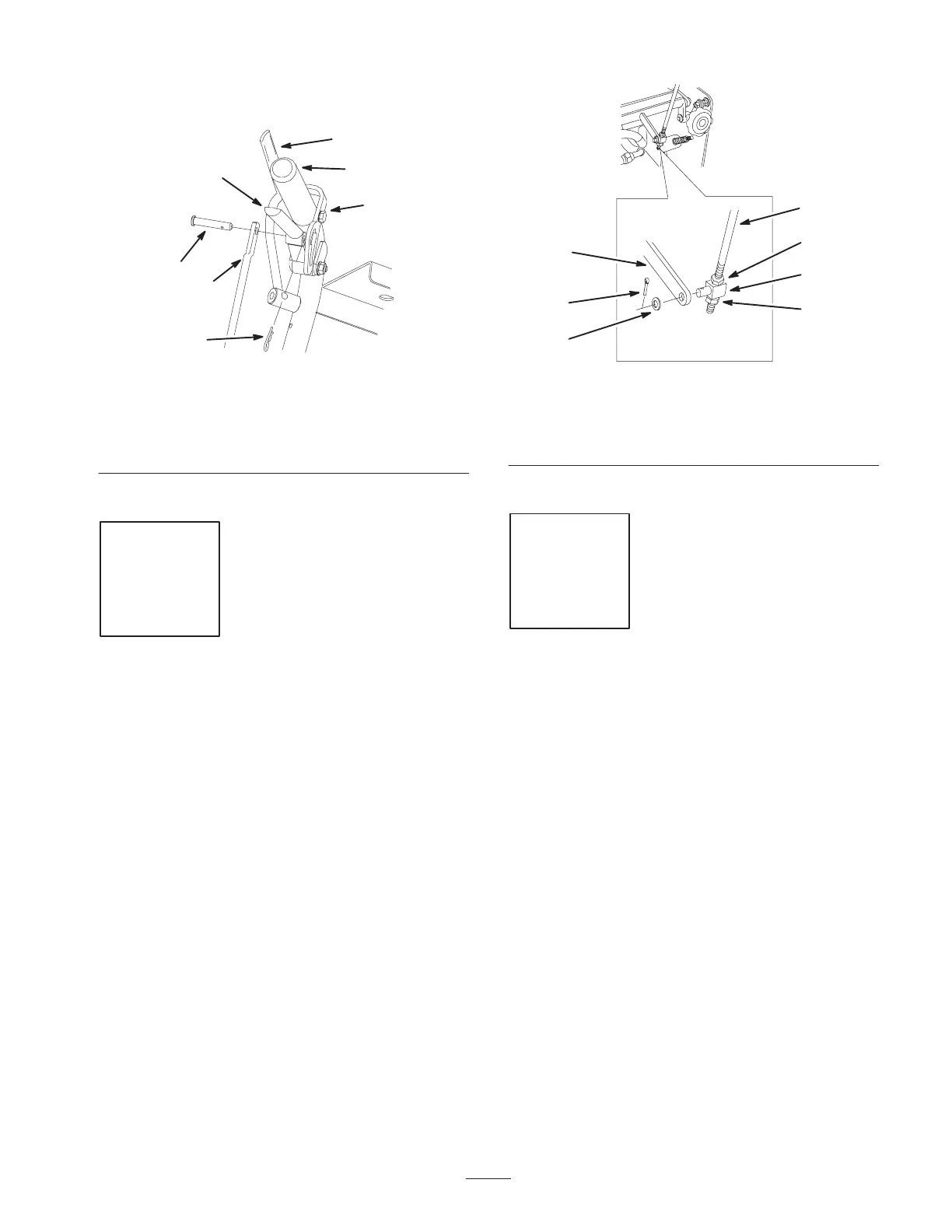
4. Install hairpin cotter pins between drive levers and
neutral locks and into clevis pins (Fig. 9).
m–6639
6
5
3
7
2
4
1
Figure 9
1. Left handle shown
2. Neutral lock
3. Clevis pin
4. Drive lever
5. Control rod
6. Operator Presence
Control lever (OPC)
7. Hairpin cotter pins
Step
5
Installing the Speed Control
Rod
Parts needed for this step:
Qty. Part
1
Washer
1
Cotter pin
Procedure
1. Install the swivel into the speed control crank and
secure it with a washer and cotter pin (Fig. 10).
Note: If necessary move the speed control lever until the
swivel will go into the speed control crank.
m–6602
1
2
3
4
5
3
6
Figure 10
1. Speed control rod
2. Swivel
3. Nut
4. Speed control crank
5. Cotter pin
6. Washer
Step
6
Installing the Hairpin Cotter
Pins and Spacers
Parts needed for this step:
Qty. Part
2
Hairpin cotter pin
6
Spacers
Procedure
Unused height–of–cut spacers may be stored on posts and
retained by a hairpin cotter.
Note: Make sure there is at least one spacer used on
eachheight–of–cut post.
1. Remove the existing rear hairpin cotter pins from the
height–of–cut posts.
 Loading...