17
Operation
Note: Determine the left and right sides of the machine
from the normal operating position.
Controls
Seat Adjusting Lever
The seat adjusting lever (Fig. 8) allows 5.9 inch (15 cm)
fore and aft adjustment in 19/32 inch (15 mm) increments.
1
Figure 8
1. Seat adjusting lever
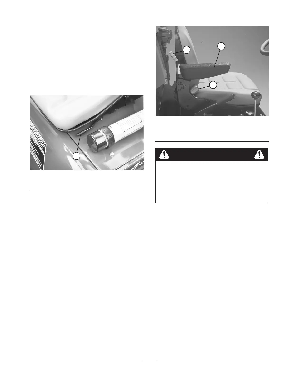
Arm Rest
Pivot the arm rest (Fig. 9) up and down for operator
comfort.
Backrest Knob
The backrest knob (Fig. 9) adjusts backrest angle from
5–20 degrees.
Suspension Lever
The suspension lever (Fig. 9) adjusts seat to the operator’s
weight. Use up position for light weight operators, center
position for medium weight operators and down for heavier
weight operators.
Note: Backrest and bottom seat cushions are removable.
1
2
3
Figure 9
1. Arm rest
2. Backrest knob
3. Suspension lever
To assure interlock switch operates properly,
seat suspension must be set for the weight of
each operator. If suspension is not set
correctly, the engine will run intermittently
and tend to stall. to correct this, set
suspension lighter.
Caution
Warning Light Test Button
Before operating machine, press warning light test button
(Fig. 10). All lights on the steering tower should illuminate.
Any light that does not come on indicates an electrical
malfunction that should be repaired immediately. Oil
pressure and electrical no charge indicator lights illuminate
when turning key switch ”ON”.
Hydraulic and Engine Indicator Lights
If these lights come on (Fig. 10), stop machine and make
repairs immediately.
 Loading...