Snow Commander Service Manual 2 - 3
CONTROLS LOCATION & OPERATION
Chute Crank
On models equipped with a chute crank, crank
clockwise to rotate the chute to the right,
counterclockwise to rotate the chute to the left (Figure
7). The chute deflector on these models is the same
as on models with a chute handle.
Figure 7
0621-0073
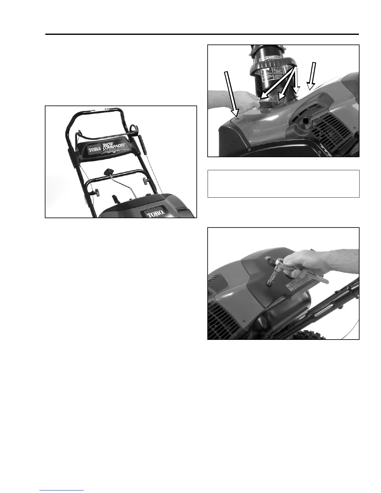
Upper Shroud Removal
The first step in many service procedures will be
removing the upper shroud for access to the engine.
Remove the three Phillips head screws, washer, and
locknuts that hold the chute and chute handle to the
chassis (Figure 8).
Remove two Phillips head screws, 4 washers, and 2
locknuts that secure the front corners of the upper
shroud (Figure 8).
Figure 8
3428-0216
Remove two 5/16” screws that hold the control panel to
the chassis (Figure 9).
Figure 9
3428-0217
Remove the fuel cap, lift the upper shroud off, and
replace the fuel cap.
Snow Commander Chute Handle System
Some Snow Commander models were equipped with a
manual chute system. As with the others, the
component parts are all plastic to eliminate the need for
lubrication and reduce icing.
(A) 2 Phillips Head
Screws, Washers,
and Locknuts
(B) 3 Phillips Head
Screws, Washers,
and Locknuts
A
B
A
 Loading...