CONTROLS LOCATION & OPERATION
2 - 4 Snow Commander Service Manual
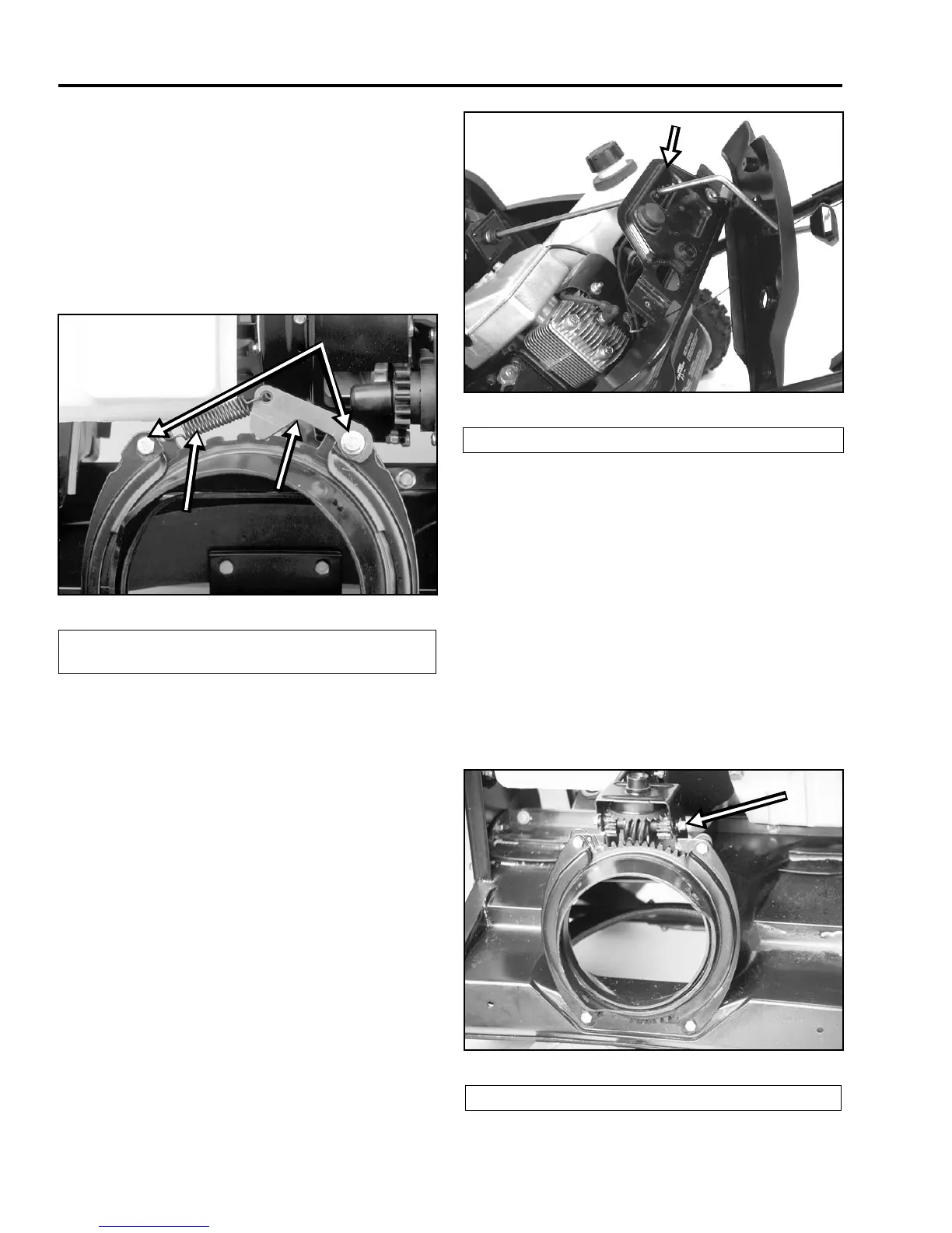
On this version, the discharge chute attaches to the
handle and chute ring. Three Phillips head bolts, nuts,
and washers connect the parts. Below the upper
shroud is the balance of the chute components.
Remove the upper shroud to access the chute ring, the
2 chute ring retainers, and the detent spring and arm
(Figure 10). To remove the chute ring, remove the four
bolts and nuts that retain the left and right chute ring
retainers.
Figure 10
1854-40
NOTE: The rear bolt in the left hand chute ring retainer
is also the pivot for the detent arm. This arm engages
the notches in the chute ring to prevent unwanted
movement. With the 4 bolts removed, the retainers and
chute ring will lift off.
Reassembly is the reverse of disassembly.
Chute Crank System
The chute crank handle goes through hole in the
control panel support (Figure 11).
Figure 11
3428-0082
Rotating the handle turns a set of gears that engage a
ring gear that the chute is mounted to. The gears are
contained in a bracket located under the upper shroud.
The chute ring gear rests on a support and is held in
place by two retainers.
To access the chute ring and gears:
1. Remove the upper shroud.
2. The gears are held in the bracket by a shaft with a
push nut on either end (Figure 12). To remove the
shaft, remove one of the push nuts and pull the
shaft out.
Figure 12
1854-19
(A) Spring
(B) Detent Arm
(C) Retainer Mounting Bolts
A
B
C
(A) Control Handle Support
(A) Shaft and Push Nut
A
A
 Loading...