Issued: 01.04.11 Approved: Mod. No. 5060358 Sheet 36 of 64 Part No. 111-4431 (A)
SAFETY CAB GENERAL ASSEMBLY - INTRODUCTION
Check that all parts have been correctly supplied.
Optional kits are also available for cab mounting, as listed below:
- Beacon Kit - Model 02843 (T4240 & R3240T Only)
- Lighting Kit (Includes tting kit) - Models 02844 & 02846 (R3240T Only)
- Lighting Kit (Includes tting kit) - Models 02844 & 02847 (LT3240 Only)
- Lighting Kit (Includes tting kit) - Models 02844 & 02845 (T4240 Only)
- Deluxe Seat - Models 02865 - Vinyl & 02866 - Fabric (All Machines listed in this Manual)
- Cab Tilt Kit - Model 02886 (All Machines listed in this Manual)
WARNING: PREVENT ACCIDENTS
- It is essential to have a suitable lifting device with a safe capacity of 350Kg.
- Always wear eye protection, gloves and use suitable breathing protection when drilling, cutting or lling
glass reinforced plastic or similar materials. Dust particles can cause extreme irritation to skin, eye, etc.
Do not inhale.
The cab must be tted by an authorised dealer.
SAFETY CAB GENERAL ASSEMBLY - ASSEMBLY
Read and understand the assembly instructions before proceed-
ing. Refer to the Operator's Manual and Spare Parts Book as
follows:
1. Lower the cutterheads to the ground.
2. Apply the parking brake, switch off the engine and remove
the ignition key.
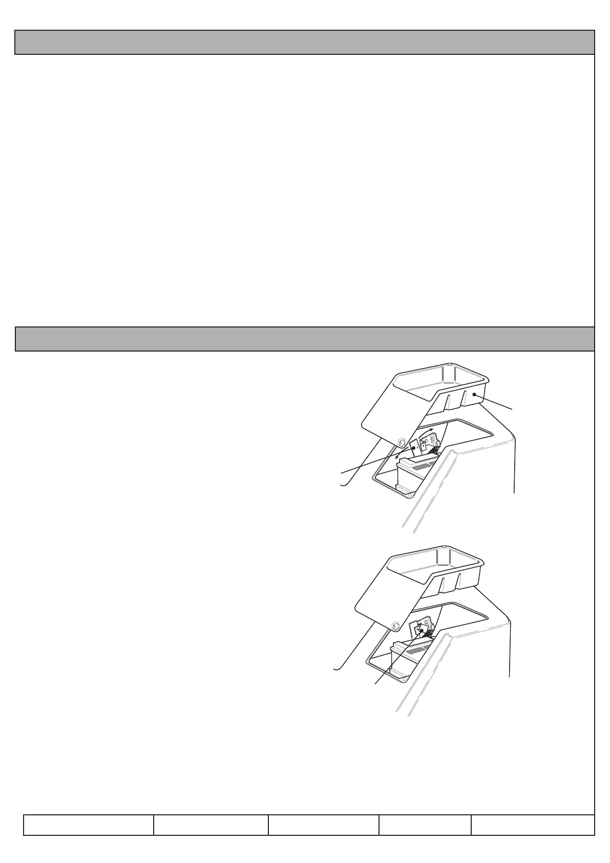
3. Remove the plastic tool tray from the platform.
Refer to Fig 26.
4. Disconnect the battery terminals, rst the negative (-ve) and
then the positive (+ve).
5. Release the padlock securing the locking latch handle with
the key provided. Move the locking latch handle towards
the front of the mower (position A) until the latch hooks
clear the locking bar. Raise the platform. The gas spring will
provide assistance. Refer to Fig 27.
Fig 26
Fig 27
1. Tool tray
2. Locking latch handle
3. Padlock
A. Releasing
B. Securing
 Loading...