Issued: 01.04.11 Approved: Mod. No. 5060358 Sheet 48 of 64 Part No. 111-4431 (A)
AIR-CONDITIONING & HEATING INSTALLATION - INTRODUCTION
The Heater Blower must be tted by an authorised dealer who is
conversant with the installation of air conditioning systems. It is
advisable to install the air conditioning before tting of the cab.
Read and understand the assembly instructions before proceed-
ing.
The complete air conditioning installation comprises of the
following:
- The evaporator matrix, heater matrix and blower
whilst mounted in the front section of the cab roof
with the condenser, fans and lter tted in the rear of
the cab roof.
- The compressor and its mounting brackets are
mounted on the engine.
- There are separate tting kits for each machine model.
LT3240 - Use tting kit Model No. 02885
T4240 - Use tting kit Model No. 02883
R3240T - Use tting kit Model No. 02884
AIR-CONDITIONING & HEATING INSTALLATION - ASSEMBLY
The below instructions are for the following machines:
LT3240, T4240 and R3240T.
1. Disconnect the battery terminals, rst the negative (-ve) and
then the positive (+ve).
2. Remove the blanking panel from under the rear extension to
the cab roof. Remove the cab roof.
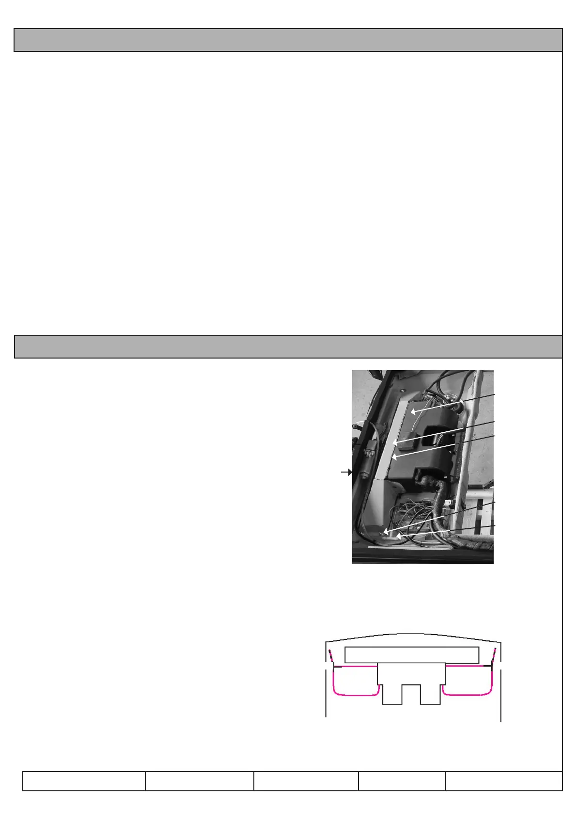
3. Fix the air conditioning and heater blower unit to the roof
insert (A). Refer to Fig 55.
4. Fix the air channel to the roof insert and against the air
conditioning and heater blower unit (B). Refer to Fig 55.
5. Seal the joint between the air channel and the heater blower
unit with a sealing compound (C). Refer to Fig 55.
6. Connect the clear condensate water pipes to the air
conditioning matrix. Using the T pieces, route (D) the pipes
through the cab roof plate and down the inside of the cab
front corner posts (E). Refer to Fig 56.
Fig 55
Front
Air con &
heater blower
unit (A)
Air channel (B)
Seal joint (C)
Bolt to cab
panel
Condenser
water pipes
Fig 56 - SHOWING PLAN VIEW OF CONDENSER
WATER HOSE T PIECE
(E) (E)
(D) (D)
 Loading...