ProductOverview
g313997
g313998
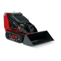
Figure3
1.Roadwheels8.Mountplate
2.Track
9.Reverse-safetyplate
3.Liftcylinder10.Controlpanel
4.Cylinderlock11.Tie-down/liftloop
5.Loaderarms12.Rear-accesscover
6.Hood
13.Sidepanelscreen
7.Auxiliaryhydraulic
couplers
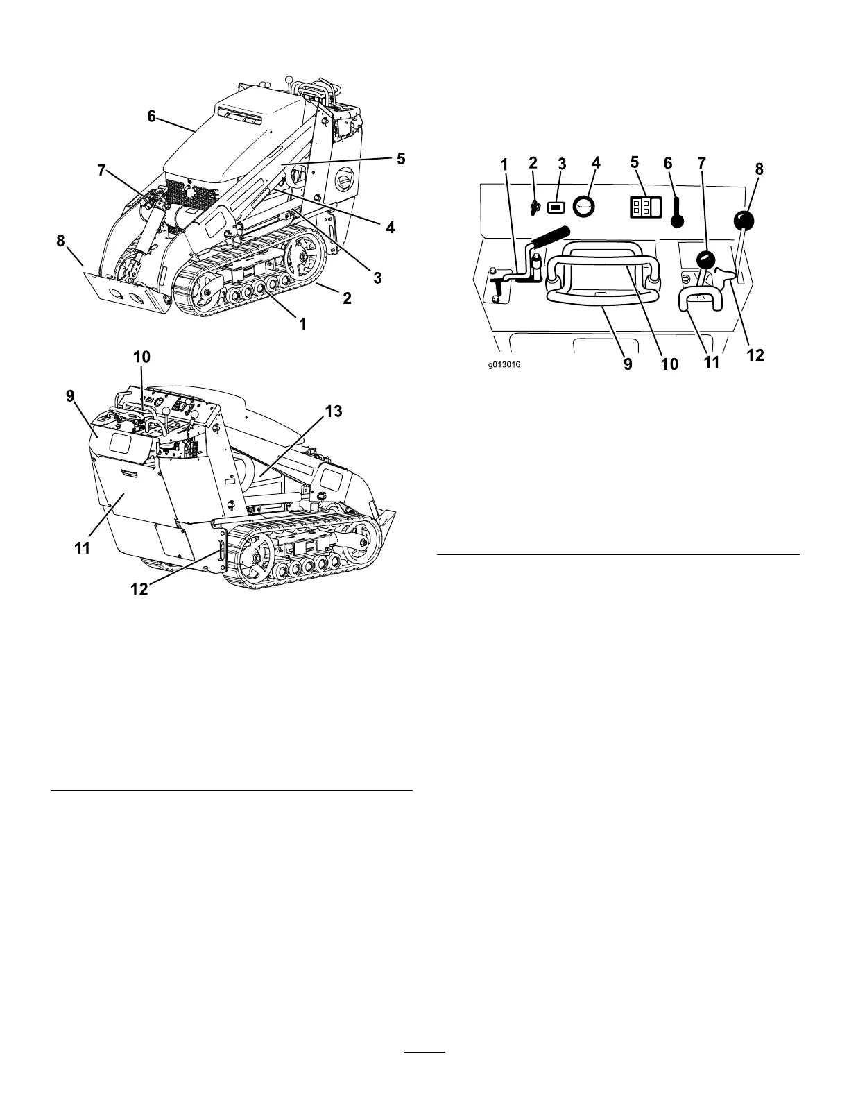
Controls
Becomefamiliarwithallthecontrols(Figure4)before
youstarttheengineandoperatethetractionunit.
ControlPanel
g013016
Figure4
1.Auxiliaryhydraulicslever
7.Loader-arm/attachment-tilt
lever
2.Keyswitch8.Parking-brakelever
3.Hourmeter9.Tractioncontrol
4.Fuelgauge
10.Referencebar
5.Indicatorlightsand
glow-plugswitch
11.Loader-control-reference
bar
6.Throttlelever12.Loader-valvelock
KeySwitch
Thekeyswitch,usedtostartandshutofftheengine,
has3positions:OFF,RUN,andSTART.Referto
StartingtheEngine(page16).
ThrottleLever
Movethecontrolforwardtoincreasetheenginespeed
andrearwardtodecreasespeed.
ReferenceBar
Whendrivingthetractionunit,usethereferencebar
asahandleandaleveragepointforcontrollingthe
tractioncontrolandtheauxiliary-hydraulicslever.T o
ensuresmooth,controlledoperation,donottake
bothhandsoffthereferencebarwhileoperatingthe
machine.
9
 Loading...


