Adjusting the
Motion-Control Linkage
Located on either side of the machine, below the seat,
are the pump-control linkages. Rotating the end nut
with a 1/2-inch deep socket wrench allows ne tuning
adjustments so that the machine does not move in
neutral. Any adjustments should be made for neutral
positioning only .
W ARNING
The engine must be running and the drive
wheels turning so that you can perform the
adjustments. Contact with moving parts or
hot surfaces may cause personal injury .
Keep your ngers, hands, and clothing clear
of rotating components and hot surfaces.
1. Park the machine on a level surface, disengage
the blade-control switch (PT O), and engage the
parking brake.
2. Shut of f the engine, remove the key , and wait
for all moving parts to stop before leaving the
operating position.
3. Push the deck-lift pedal, remove the height-of-cut
pin, and lower the mower deck to the ground
4. Raise the rear of the machine up and support it
with jack stands (or equivalent support) just high
enough to allow the drive wheels to turn freely .
5. Remove the electrical connection from the seat
safety switch, located under the bottom cushion
of the seat.
Note: The switch is a part of the seat assembly .
6. T emporarily install a jumper wire across the
terminals in the connector of the main wire
harness.
7. Start the engine, run it at full throttle, and
disengage the parking brake.
Note: Before starting the engine, ensure that
the parking brake is engaged and that the
motion-control levers are out. Y ou do not have
to be in the seat.
8. Run the machine at least 5 minutes with the
drive levers at full forward speed to bring the
hydraulic uid up to the operating temperature.
Note: The motion-control levers must be in
neutral while you are making any adjustments.
9. Bring the motion-control levers into the N EUTRAL
position.
10. Check and ensure that the control-plate tabs
touch the return-to-neutral plates on the
hydraulic units.
1 1. Adjust the pump-control-rod lengths by rotating
the nut in the appropriate direction until the
wheels slightly creep in reverse ( Figure 81 and
Figure 82 ).
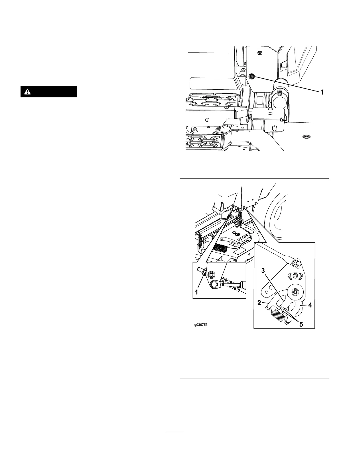
g334848
Figure 81
1. Access hole for 1/2-inch socket
g036753
Figure 82
1. Nut 4. Return-to-neutral plate
2. Stationary plate
5. T abs touching return to
neutral plate
3. Control plate
12. Move the motion-control levers to the R EVERSE
position and while applying slight pressure to
the lever , allow the reverse-indicator springs to
bring the levers back to neutral.
61

 Loading...

