g298850
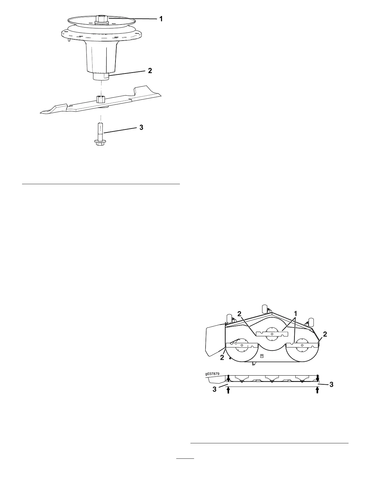
Figure 97
1. T op spindle nut 3. Blade bolt
2. Flat of the spindle shaft
3. Apply copper-based lubricant or grease to the
threads of the blade bolt as needed to prevent
seizing. Install the blade bolt nger-tight.
4. Place a wrench on the at of the spindle shaft
and torque the blade bolt to 75 to 81 N∙m (55
to 60 ft-lb).
Adjusting the Side-to-Side
Leveling and the Blade
Slope
Check to ensure that the mower deck is level any time
you install the mower or when you see an uneven cut
on your lawn.
Check the mower deck for bent blades prior to
leveling, and remove and replace any bent blades;
refer to Checking for Bent Blades ( page 67 ) before
continuing.
Level the mower deck side-to-side rst; then you can
adjust the front-to-rear slope.
Requirements:
• The machine must be on a level surface.
• All tires must be properly inated; refer to Checking
the T ire Pressure ( page 57 ) .
1. Park the machine on a level surface, disengage
the blade-control switch (PT O), and engage the
parking brake.
2. Shut of f the engine, remove the key , and wait
for all moving parts to stop before leaving the
operating position.
3. Check the tire pressure in the drive tires; refer to
Checking the T ire Pressure ( page 57 ) .
4. Position the mower deck in the transport-lock
position or the highest height-of-cut setting.
5. Carefully rotate the blades from side to side.
6. Measure between the blade tip and the at
surface ( Figure 98 ). If both measurements are
not within 5 mm (3/16 inch), adjust the leveling;
continue with this procedure.
g037879
Figure 98
1. Blades side to side
3. Measure from the tip of the
blade to the at surface
here.
2. Blade tip
69

 Loading...

