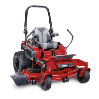
7. Check the front-to-rear blade level ( Figure 99 ).
Ensure the front blade tip is lower than the rear
blade tip as shown in the block height and rake
table. If adjustment is needed, continue with this
procedure.
g037880
Figure 99
1. Blades front to rear 3. Measure from the tip of the
blade to the at surface
here.
2. Blade tip
8. Set the anti-scalp rollers to top holes or remove
them completely for this adjustment.
9. Raise the deck to the transport position (140 mm
or 5-1/2 inches).
10. Slowly loosen the adjusting screw on the
lift-assist spring until you can remove the screw
( Figure 100 ).
Note: Save the screw for installation.
g334850
Figure 100
1. Adjusting screw
3. Set the gap to 22 to 29
mm (7/8 to 1-1/8 inches).
2. Bracket
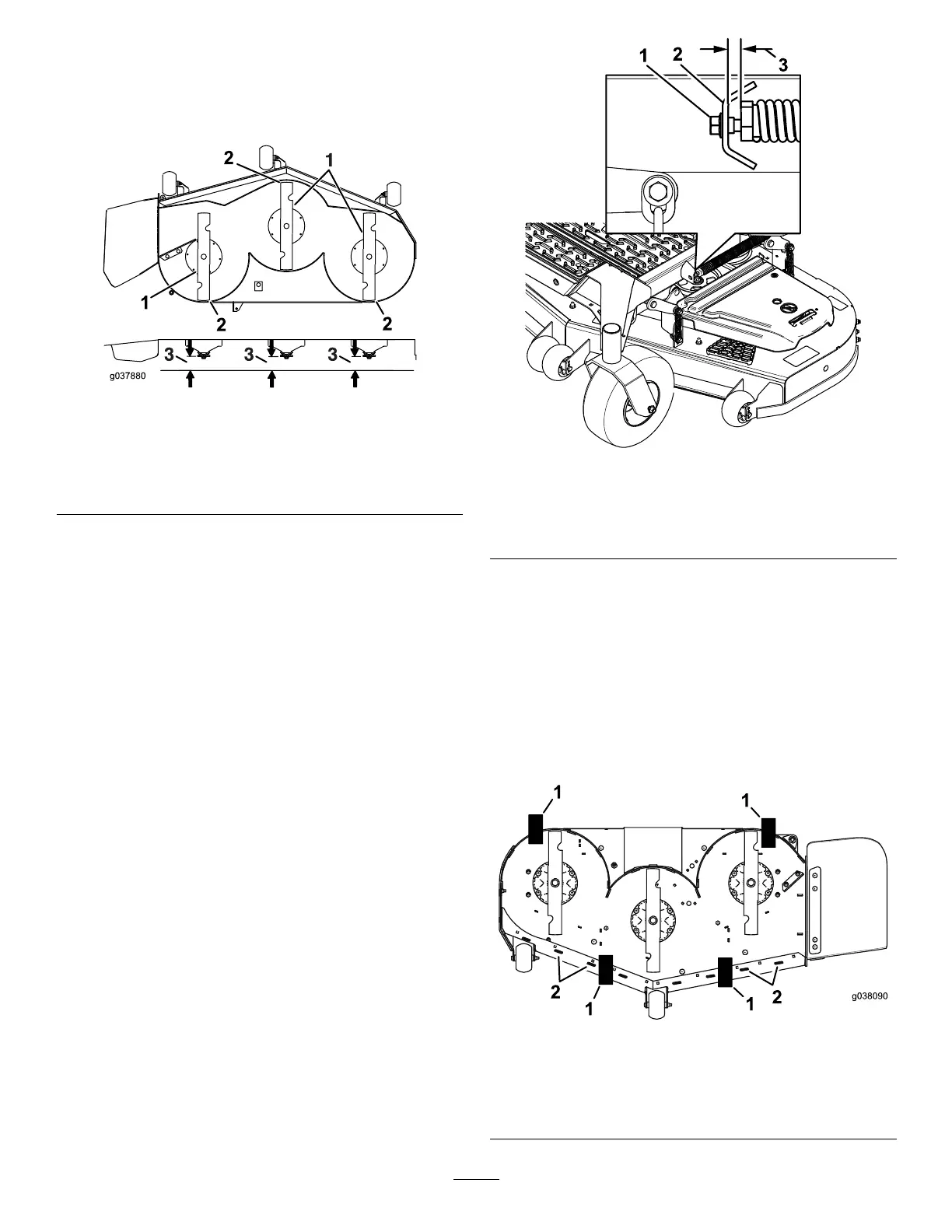
1 1. Place 2 blocks (see Block Height and Rake
T able) under the rear edge of the cutting deck
skirt; 1 on each side of the cutting deck ( Figure
101 ).
12. Set the height-of-cut lever to the 76 mm (3
inches) position; refer to Adjusting the Height
of Cut ( page 29 ) .
13. Place 2 blocks under each side of the front edge
of the deck, but not under the anti-scalp roller
brackets or welds.
g038090
Figure 101
Bottom view
1. Block—73 mm (2-7/8
inches)
2. W elds
70
 Loading...

