EasyManua.ls Logo

Toshiba 1600XP SERIES User Manual

Toshiba 1600XP SERIES
140 pages
To Next Page IconTo Next Page
To Previous Page IconTo Previous Page
Page #14 background imageLoading...
Page #14 background image
4
1600XP/XPi Series Installation and Operation Manual – 60616-012
1
L1
(L*)
2
L2
(N*)
3
G
4
X1
5
X2
6
N
(0V*)
7
X3
8
G
11
208V
12
COM
13
240V
14
EPO1
15
EPO2
16
REMOTE
17
REMOTE
USECOPPER90 CONDUCTORSONLY.REFERTOINSTRUCTIONMANUALREGARDINGTORQUEOFTERMINALBLOCKS.FACTORYWIREDFOR208VINPUT.
o
208/240V
208V
120V
240V
120V
INPUTVOLTAGE
JUMPERSELECTION
EPO REMOTE
INPUT
OUTPUT
(*)FORSINGLEHOTWIRE
P/N63093 - Power Terminal Label
P/N 63109 – There are no user-serviceable parts
behind cover. Wait ve minutes after disconnect-
ing the UPS to allow the internal capacitors to
discharge completely.
Date of last recorded battery change.
Battery Cabinet Warning Label.
* For reference only, DC voltage varies by
kVA size of the UPS.

Table of Contents

Other manuals for Toshiba 1600XP SERIES

Question and Answer IconNeed help?

Do you have a question about the Toshiba 1600XP SERIES and is the answer not in the manual?

Toshiba 1600XP SERIES Specifications

General IconGeneral
BrandToshiba
Model1600XP SERIES
CategoryUPS
LanguageEnglish

Summary

Product Use and Warranty Restrictions

QUALIFIED PERSONNEL ONLY

Defines personnel qualified for electrical equipment installation, operation, and maintenance.

2. Equipment Warning Labels

Purpose

3. Important Safety Instructions

3.1 Qualified Personnel Only

Defines requirements and responsibilities for qualified personnel.

Toshiba Customer Support Center

1. General Safety Instructions

1.1 Symbols

Explains safety symbols used throughout the manual.

1.2 Signal Words

Defines signal words like DANGER, WARNING, CAUTION, NOTICE.

1.3 Regulatory Compliance Statement

FCC Class A notice and EMC Directive Class A note.

4. Inspection/Storage/Disposal

Inspection

Inspects the unit for shipping damage upon receipt.

Unpacking

Checks for damage and verifies model/capacity after unpacking.

Storage

Provides guidelines for storing the UPS during periods of non-use.

Disposal

Advises on proper disposal of electrical components and batteries.

5. Installation Precautions

NOTICE

Highlights environmental restrictions for UPS installation.

6. Conductor Routing and Grounding

7. Operating Precautions

8. UPS Connections

8.1 Terminal Block - 208/240 VIN, 120/280/240 VOUT

Details terminal block and wiring for 208/240V units.

8.2 Terminal Block - 240 VIN, 100/200 VOUT

Details terminal connections for 240V input, 100/200V output units.

8.3 EPO and Remote Shutdown

Explains Emergency Power Off and Remote Shutdown functions.

8.4 Cable Size and Tightening Torque

Provides recommended wire sizes and tightening torques for connections.

8.5 Battery Cabinet Connections

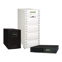
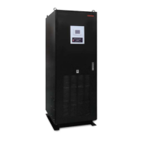
Describes connecting external battery cabinets for extended backup.

9. Product Description

9.1 Application and Use

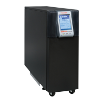
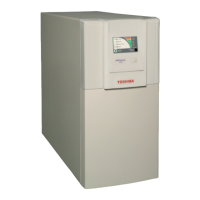
Describes the UPS's application and intended use.

9.2 Output Rating

Lists UPS models and their output capacities.

9.3 Power Backup

Explains how the UPS provides backup power during outages.

9.4 Power Conditioning

Describes the UPS's protection against power disturbances.

10. Operating Modes

10.1 Static-Bypass (Stop operation)

Explains the UPS operation in Static-Bypass mode due to overload or fault.

10.2 On-Line (Run operation)

Describes normal UPS operation in On-Line mode.

10.3 Battery Backup (On batteries)

Details power flow during battery backup mode.

10.4 EPO (Emergency Power Off) Function

Explains the function and use of the Emergency Power Off feature.

10.5 Battery Backup Time and Discharge Process

Illustrates battery discharge and backup time factors.

10.6 Battery Low Voltage Tolerances

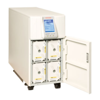
Lists voltage levels for alarms and shutdown.

10.7 Battery Recharging

Describes the battery recharge process and parameters.

10.8 Battery Test

Details procedures for automatic and manual battery tests.

11. Operating the UPS

11.1 Initial Startup (First Power-Up)

Guides through initial setup and parameter configuration upon first activation.

11.2 Battery Parameter Settings

Covers settings for battery parameters with different cabinet configurations.

12. Display and Keys

12.1 Front Panel Layout

Identifies and illustrates front panel components for monitoring and operation.

12.2 Display Manual Controls

Explains manual controls on the display and front panel.

13. LCD Touchscreen Layout

13.1 Startup Display

Describes the default startup screen and its functions.

13.2 Operating Keys

Identifies touch-sensitive keys and their functions on the touchscreen.

13.3 Status Indicators

Explains the meaning of various status indicators on the main screen.

13.4 Light Emitting Diodes (LED)

Describes the behavior and significance of front panel LEDs.

14. Touchscreen Menu Tree

14.1 Front Panel Layout

Illustrates the menu tree structure for the touchscreen display.

14.2 Keypad Controls

Explains the use of the alphanumeric keypad for input.

14.3 Screen: Security Passwords & Keypad

Details security levels, login, and password entry.

14.4 Forget/Reset Password

Provides steps to reset the ADMIN password.

15. Screen Tab: Main

16. Screen Tab: Monitor

16.1 Records

Explains how to access and page through stored records.

16.2 Audible Alarm Functions

Details audible alarm patterns and their conditions.

17. Screen Tab: Settings

17.1 Changing UPS Parameter Settings

Guides on how to change various UPS operating parameters.

17.2 Settings Parameters

Lists settings parameters, access levels, and their descriptions.

17.3 Recalibrate the Touchscreen

Provides steps to recalibrate the touchscreen display for accuracy.

18. Communication Interfaces

18.1 Remote Contacts

Describes the pin assignment and current carrying capacity of remote contacts.

18.2 UPS LAN Shutdown Signal Operation

Explains how LAN shutdown signals operate the UPS.

18.3 RS-232C

Details the RS232C port pin assignment and its use.

18.4 RemotEye Network Card

Describes the RemotEye network card for remote management.

18.5 (Optional) EMD

Explains the Environmental Monitoring Device and its sensors.

19. Optional MB (Maintenance Bypass) Units

19.1 Internal Maintenance Bypass

Provides instructions for using the internal maintenance bypass.

20. Optional TVSS (Transient Voltage Surge Suppressor)

21. External Battery Cabinet Connections

22. Optional Receptacle Panel Installation Instructions

23. UPS Protection System

23.1 UPS Protection Devices

Shows the schematic locations of UPS protection devices.

23.2 UPS Protection Devices Fault Response

Details UPS responses to common faults like overvoltage and overload.

23.3 System Fault Messages

Lists possible fault messages and recommended actions.

23.4 System Warning Messages

Lists warning messages and their meanings.

23.5 System Mode Messages

Lists possible operating modes for the UPS.

23.6 System Status Messages

Lists possible status messages and their meanings.

24. Preventive Maintenance/Parts Replacement

24.1 Preventive Maintenance

Covers basic preventive maintenance for UPS units.

24.2 Cleaning the Touchscreen

Instructions for cleaning the touchscreen display.

24.3 Battery Pack Replacement

Details the process for replacing internal battery packs.

24.4 Part Replacement

Lists recommended replacement intervals for UPS parts.

25. External Layouts/Dimensions/Shipping Weights

25.1 Electrical Conduit Knock-out Data

Provides electrical conduit knock-out hole sizes by kVA.

25.2 Unit and Shipping Weights

Lists unit and shipping weights in pounds and kilograms.

25.3 Dimensional Data

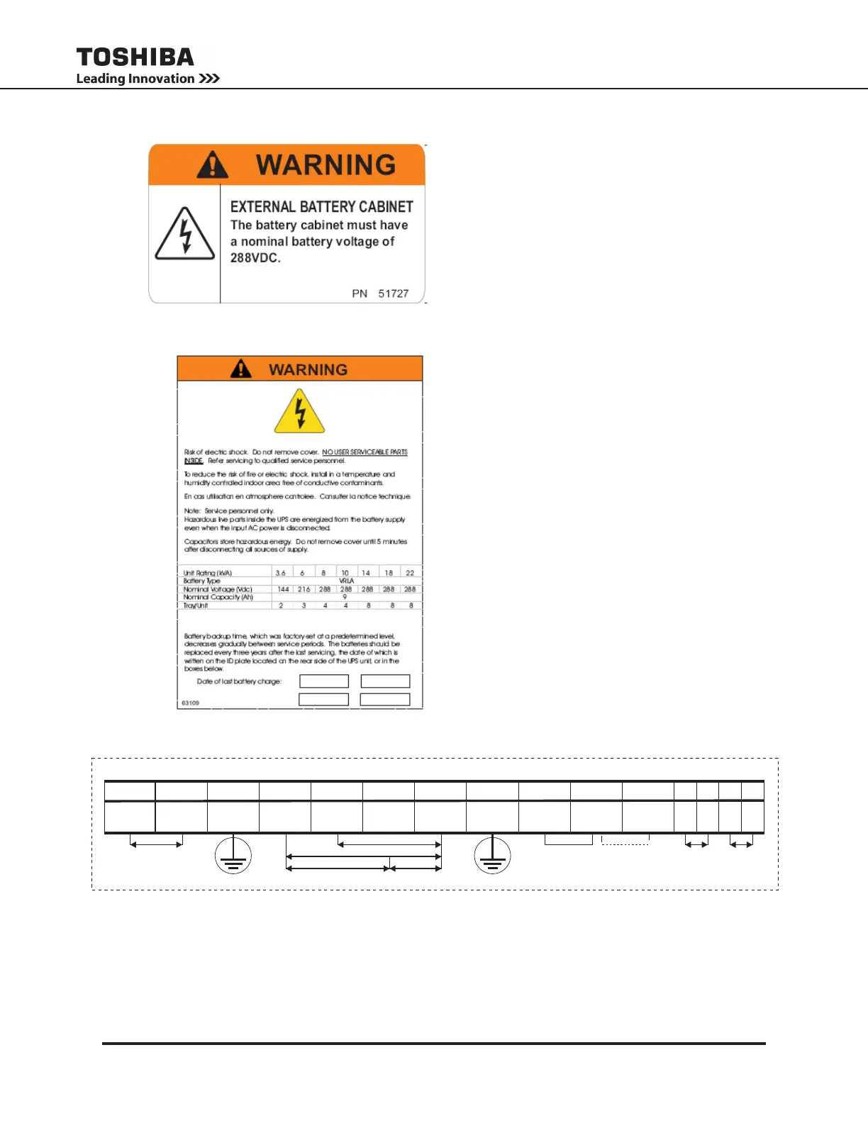
Presents dimensional data in inches and millimeters for different kVA units.

25.4 External Layout

Shows external layouts and dimensions for different kVA units.

Related product manuals