2460 ADJUSTMENT 1 - 42 September 1997 © TOSHIBA CORP.
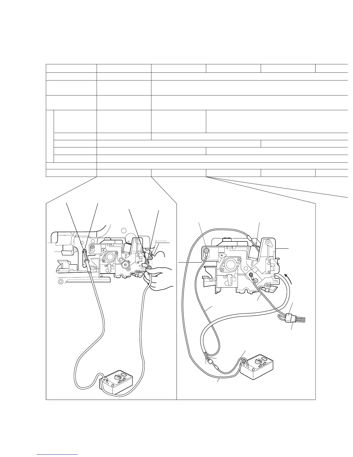
1.9 High-Voltage Adjustment
1.9.1 Adjustment
(1) Measurement
Developer unit
Cleaner unit
Dev.unit connector of
the machine
(+) terminal
(–) terminal
Function switch
Full-scale
Remarks
How to turn the power ON
Developer Bias Main Charger Transfer Charger Separation Charger
Pull out the connector.
Remove the drum.
Install the Developer unit.
Not connect
Connect to the bias
measuring hole (B) of the
Developer unit.
Connect to (A)
Connect to the main
charger case. (between
the case and the terminal)
Connect to red cable of Current measuring jig.
Connect to the white cable of the current measuring Jig (frame grounding).
DC
AC
1,000 V
2V
Use a digital tester having an input resistance of 10 MΩ (RMS value) or more.
Developer Bias Main Charger Transfer Separation
Use the door switch jig.
Remove from the copier. (Not use)
Mount on the machine with a current measuring jig.
NOTES 1: Connect the green code of the current measuring jig to earth on the copier.
Connect the jig detection connector to the Dev.unit connector of the copier.
Digital Tester
d terminal e terminal
e
(A)
Machine frame
(frame grounding)
d terminal
e terminal
Green
Red
White
Brown
d
(B)
Main charger case
Current
measuring
jig
Dev. unit connector
of the copier
Jig detection
connector
(Frame
grounding)
 Loading...