EasyManua.ls Logo

Toshiba 29CZ5DE User Manual

Toshiba 29CZ5DE
50 pages
To Next Page IconTo Next Page
To Previous Page IconTo Previous Page
Page #8 background imageLoading...
Page #8 background image
GENERAL ADJUSTMENTS
– 8 –
SERVICE MODE
1. ENTERING TO SERVICE MODE
1) Press o button once on
Remote Control.
2. DISPLAYING THE ADJUSTMENT MENU
1) Press MENU button on TV.
3. KEY FUNCTION IN THE SERVICE MODE
The following key entry during display of adjustment menu provides special functions.
A single horizontal line ON/OFF: - / - - button (on remote control)
Test signal ON/OFF : a button (on TV or remote control)
Selection of the adjustment items : Channel s/t (on TV or remote control)
Change of the data value : Volume ; +/– (on TV or remote control)
Adjustment menu mode ON/OFF : MENU button (on TV)
Initialization of the memory (QA10) : CALL + Channel button on TV (s)
Reset the count of operating protect
circuit to “00”: CALL + Channel button on TV (t)
“VG2 alignment : 0 button
“BCUT” selection : 1 button
“GCUT” selection : 2 button
“SCNT” selection : 4 button
“COLC” selection : 5 button
“TNTC” selection : 6 button
“SBY” selection : 7 button
Self diagnostic display ON/OFF : 9 button
CAUTION : Never try to perform initialization unless you have changed the memory IC.
2) Press o button again to
keep pressing.
3) While pressing the o button,
press MENU button on TV.
Color thickness correction
note: Displayed differently as shown below, depending
on the setting of the receiving color system.
COLP (PAL)
COLC (NTSC)
COLS (SECAM)
S
(Service mode display)
Item
Data
Adjustment mode
Press
Press
Service mode
Item
Data
S
Question and Answer IconNeed help?

Do you have a question about the Toshiba 29CZ5DE and is the answer not in the manual?

Toshiba 29CZ5DE Specifications

General IconGeneral
BrandToshiba
Model29CZ5DE
CategoryTV
LanguageEnglish

Summary

General Adjustments

Safety Instructions

Precautions for X-ray radiation, high voltage, and general safety during servicing.

Set-up Adjustment

Color Purity Adjustment

Procedure to adjust color purity using the deflection yoke and magnets.

Center Convergence Adjustment

Adjusting 4-pole and 6-pole magnets for central image convergence.

Circumference Convergence Adjustment

Adjusting deflection yoke position for circumference convergence.

Set-up Adjustment (Flat Tube)

Color Purity Adjustment (Flat Tube)

Adjusting color purity for flat tube TVs using yoke and magnets.

Convergence Adjustments (Flat Tube)

Adjusting convergence for flat tube TVs using magnets and yoke.

Circumference Convergence (Flat Tube)

Detailed steps for circumference convergence adjustments on flat tube TVs.

Service Mode

Entering and Operating Service Mode

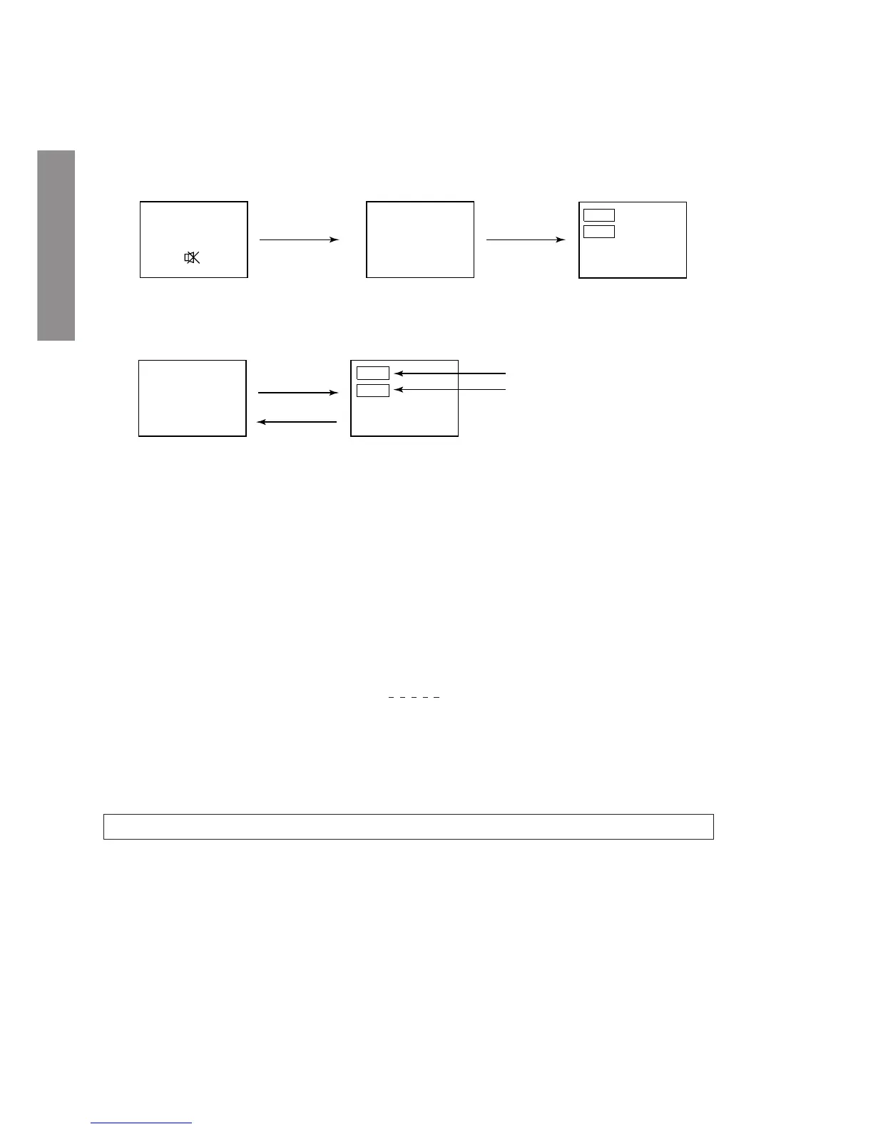
Guide to access and use the service mode for TV adjustments.

Design Mode

Entering and Operating Design Mode

Guide to access and use the design mode for model-specific settings.

Electrical Adjustments

Focus VR and Sub-Brightness Adjustment

Adjusting focus and sub-brightness (BRTC) for picture quality.

Horizontal and Vertical Position Adjustment

Adjusting horizontal (HPOS) and vertical (VPOS) picture position.

Vertical Amplitude Adjustment

Adjusting vertical picture amplitude (HIT) for optimal display.

White Balance Adjustment

Adjusting white balance in high and low light areas for accurate colors.

Circuit Check

High Voltage Check Procedure

Procedure for checking high voltage and ensuring it's within limits.

Specific Informations

Setting & Adjusting Data

Table of adjustment items, reference data, and adjust data for service mode.

Names and Functions of Controls

Identification and description of TV front panel and remote control buttons.

Programming Channel Memory

Procedures for automatically setting and manually programming TV channels.

Procedures to Set Hotel Mode

Steps to configure the TV for hotel operation, including channel setup and volume limits.

Chassis and Cabinet Replacement Parts List

Capacitors

List of capacitor part numbers, descriptions, and locations for chassis/cabinet.

Resistors

List of resistor part numbers, descriptions, and locations for chassis/cabinet.

Coils & Transformers

List of coil and transformer part numbers, descriptions, and locations.

Semiconductors

List of semiconductor part numbers, descriptions, and locations.

Miscellaneous Parts

List of miscellaneous components like fuses, cables, and sockets.

PC Board Assemblies

List of PC board assembly part numbers and descriptions.

Picture Tube

Part number and description for the picture tube.

Tuner

Part number and description for the TV tuner.

Accessories

List of accessories like carton box, remote control, and manuals.

Cabinet Parts

List of cabinet part numbers, descriptions, and locations.

Terminal View of Transistors

Transistor Terminal Configurations

Diagrams showing the pin configurations (E, B, C) of various transistors.

Schematic Diagram

Schematic Diagram Structure

Overview of the schematic diagram sections and their corresponding page references.

Circuit Block Diagram

Block Diagram Overview

A high-level block diagram illustrating the main functional blocks of the TV.

Specifications

Model Specifications

Technical specifications including voltage, power, dimensions, mass, and picture tube details.

Television System Coverage

Details on supported television systems and channel coverage for different regions.

Color System and Sound Output

Information on supported color systems and audio output specifications.

Terminals

Description of the various input and output terminals on the TV.

Schematic Diagram Section 1/8

Signal/Micon Circuit

Schematic details for the Signal/Micon main circuit.

Schematic Diagram Section 2/8

Main Vertical Circuit

Schematic details for the main vertical circuit of the TV.

Schematic Diagram Section 3/8

Main Horizontal Circuit

Schematic details for the main horizontal circuit of the TV.

Schematic Diagram Section 4/8

Main Protector Circuit

Schematic details for the main protector circuit of the TV.

Schematic Diagram Section 5/8

Main Low B Regulation Circuit

Schematic details for the main low B regulation circuit.

Schematic Diagram Section 6/8

Main Power Circuit

Schematic details for the main power supply circuit of the TV.

Schematic Diagram Section 7/8

CRT Drive Circuit

Schematic details for the CRT drive circuit.

Schematic Diagram Section 8/8

Front Circuit

Schematic details for the front panel circuitry of the TV.

Related product manuals