EasyManua.ls Logo

Toshiba RAS-10GAVP-E User Manual

Toshiba RAS-10GAVP-E
116 pages
To Next Page IconTo Next Page
To Previous Page IconTo Previous Page
Page #16 background imageLoading...
Page #16 background image
16
4-2. Outdoor Unit
RAS-10GAVP-E, RAS-13GAVP-E, RAS-16GAVP-E
Pipe dia. Ø9.52:RAS-10GAVP-E, RAS-13GAVP-E
Ø12.7:RAS-16GAVP-E
2-Ø20x88 drain long hole
leg part
Ø25 drain hole
Ø11-14U-shape hole
(for Ø8-Ø10 anchor bolt)
Connecting pipe port
(Pipe dia. Ø6.35)
8-Ø7 hole
(for fixing outdoor unit)
Ø11x14 long hole
(for Ø8-Ø10 anchor bolt)
Packed valve cover
Charging port
Outside line
of product
Outside line
of product
Outside line
of product
4-Ø4.5 embossment
Fin guard
Fan guard
Mounting dimensions of anchor bolt
When installing the outdoor unit,
leave open in at least two of
directions (A), (B), (C) and (D)
shown in the figure below.
A
leg part
B
320
306
290
145.5
(Anchor bort
long hole pitch)
Ø7 hole pitch
30
54
108
600 90
125
60
30
20
( )
69.5 147
31 143
342
483
257
108
137
320
93
145
Z
157 79
218
71
780
50032
25
22
54
21
600
52
35
449
483 6
550
600
600
38
38
320 320
54
54
11
11
R5.5
R5.5
R15
2-
Ø7 hole
2-Ø7 hole
R15
Detailed leg part
A
Detailed leg part
B
view
Z
D
B
C
250 or more
Minimum distance
from wall
2-Ø11x14 long hole
(for Ø8-Ø10 anchor bolt)
2-Ø11x14U- Shape hole
(for Ø8-Ø10 anchor bolt)
Intake
Intake
Outlet
50 or more
200 or more
100 or more
A

Table of Contents

Question and Answer IconNeed help?

Do you have a question about the Toshiba RAS-10GAVP-E and is the answer not in the manual?
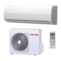
Toshiba RAS-10GAVP-E Specifications

General IconGeneral
TypeSplit System
Cooling Capacity2.5 kW
Heating Capacity3.2 kW
Power Supply220-240V, 50Hz
RefrigerantR410A
Energy Efficiency Ratio (EER)3.21
Coefficient of Performance (COP)3.61
Indoor Unit Dimensions (W x H x D)798 x 293 x 230 mm
Indoor Unit Weight9 kg
Noise Level (Outdoor Unit)49 dB(A)

Summary

1. SAFETY PRECAUTIONS

New Refrigerant Air Conditioner Installation

Safety precautions for installing R410A air conditioners.

2. SPECIFICATIONS

General Specifications

Detailed technical specifications for indoor and outdoor units.

Operation Characteristic Curves

Graphical representation of cooling and heating performance curves.

Capacity Variation by Temperature

Shows how capacity changes with outdoor temperature.

3. REFRIGERANT R410A

Safety During Installation and Servicing

Safety precautions for handling R410A refrigerant during installation and servicing.

Refrigerant Piping Installation

Guidelines for installing refrigerant piping, including materials and joints.

Required Tools

Lists tools necessary for R410A installation and servicing.

4. CONSTRUCTION VIEWS

Indoor Unit Construction Views

Exploded views and diagrams of the indoor unit's internal components.

Outdoor Unit Construction Views

Exploded views and diagrams of the outdoor unit's internal components.

5. WIRING DIAGRAM

Outdoor Unit Wiring Diagram

Electrical wiring schematic for the outdoor unit.

Indoor Unit Wiring Diagram

Electrical wiring schematic for the indoor unit.

6. SPECIFICATIONS OF ELECTRICAL PARTS

Indoor Unit Electrical Parts Specifications

List of indoor unit electrical components and their specifications.

Outdoor Unit Electrical Parts Specifications

List of outdoor unit electrical components and their specifications.

7. REFRIGERANT CYCLE DIAGRAM

Refrigerant Cycle Diagram

Schematic showing the refrigerant flow and system components.

Operation Data

Data on operating conditions, pressures, temperatures, and fan speeds.

8. CONTROL BLOCK DIAGRAM

Indoor Unit Control Block Diagram

Diagram illustrating control logic and signal flow within the indoor unit.

Outdoor Unit Control Block Diagram

Diagram illustrating control logic and signal flow within the outdoor unit.

9. OPERATION DESCRIPTION

Outline of Air Conditioner Control

Overview of the air conditioner's control system and component functions.

Detailed Operation Modes

Explains various operation modes like Cooling, Heating, AUTO, DRY, ECO.

10. INSTALLATION PROCEDURE

Installation Safety Cautions

Important safety warnings and precautions for installation.

Optional Parts, Accessories, and Tools

Lists optional parts, accessories, and necessary tools for installation.

Indoor Unit Installation

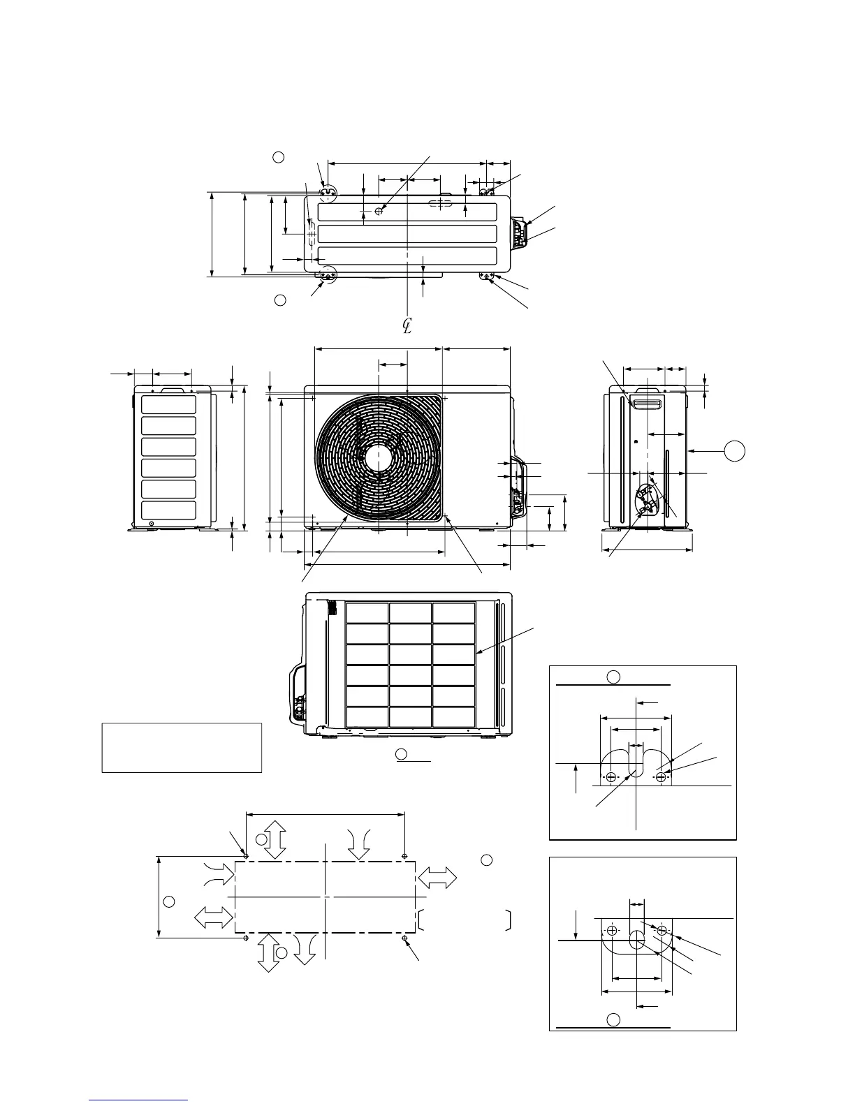
Detailed steps and considerations for installing the indoor unit.

Outdoor Unit Installation

Detailed steps and considerations for installing the outdoor unit.

11. HOW TO DIAGNOSE THE TROUBLE

Initial Confirmation Steps

Preliminary checks for power supply and basic operation.

Indoor Unit LED Flashing Judgment

Interpreting flashing LED codes for indoor unit self-diagnosis.

Remote Controller Self-Diagnosis

Using remote controller service mode to retrieve check codes for diagnosis.

Wiring Failures

Troubleshooting guide for interconnecting and serial signal wiring issues.

Inverter Assembly Diagnosis

Diagnostic flowchart for the outdoor unit inverter assembly.

Indoor Unit P.C. Board Check

Procedures for checking the indoor unit's Printed Circuit Board.

Outdoor Fan Motor Check

Steps to diagnose the outdoor fan motor's functionality.

12. HOW TO REPLACE THE MAIN PARTS

Indoor Unit Part Replacement

Procedures for replacing main parts of the indoor unit.

Microcomputer Replacement

Procedure for replacing the microcomputer assembly.

Outdoor Unit Part Replacement

Procedures for disassembling and attaching outdoor unit components.

13. EXPLODED VIEWS AND PARTS LIST

Indoor Unit Exploded Views and Parts List

Exploded diagrams and parts list for the indoor unit.

Outdoor Unit Exploded Views and Parts List

Exploded diagrams and parts list for the outdoor unit.

P.C. Board Layout

Diagram showing component layout on the Printed Circuit Board.

Cord Heater Installation Work

Required Parts for Cord Heater Installation

List of recommended parts for cord heater installation.

Required Tools for Cord Heater Installation

List of tools needed for cord heater installation.

Cord Heater Wiring Diagram

Wiring diagram for the cord heater installation.

Cord Heater Installation Procedure

Step-by-step guide for installing the cord heater.

Related product manuals