38
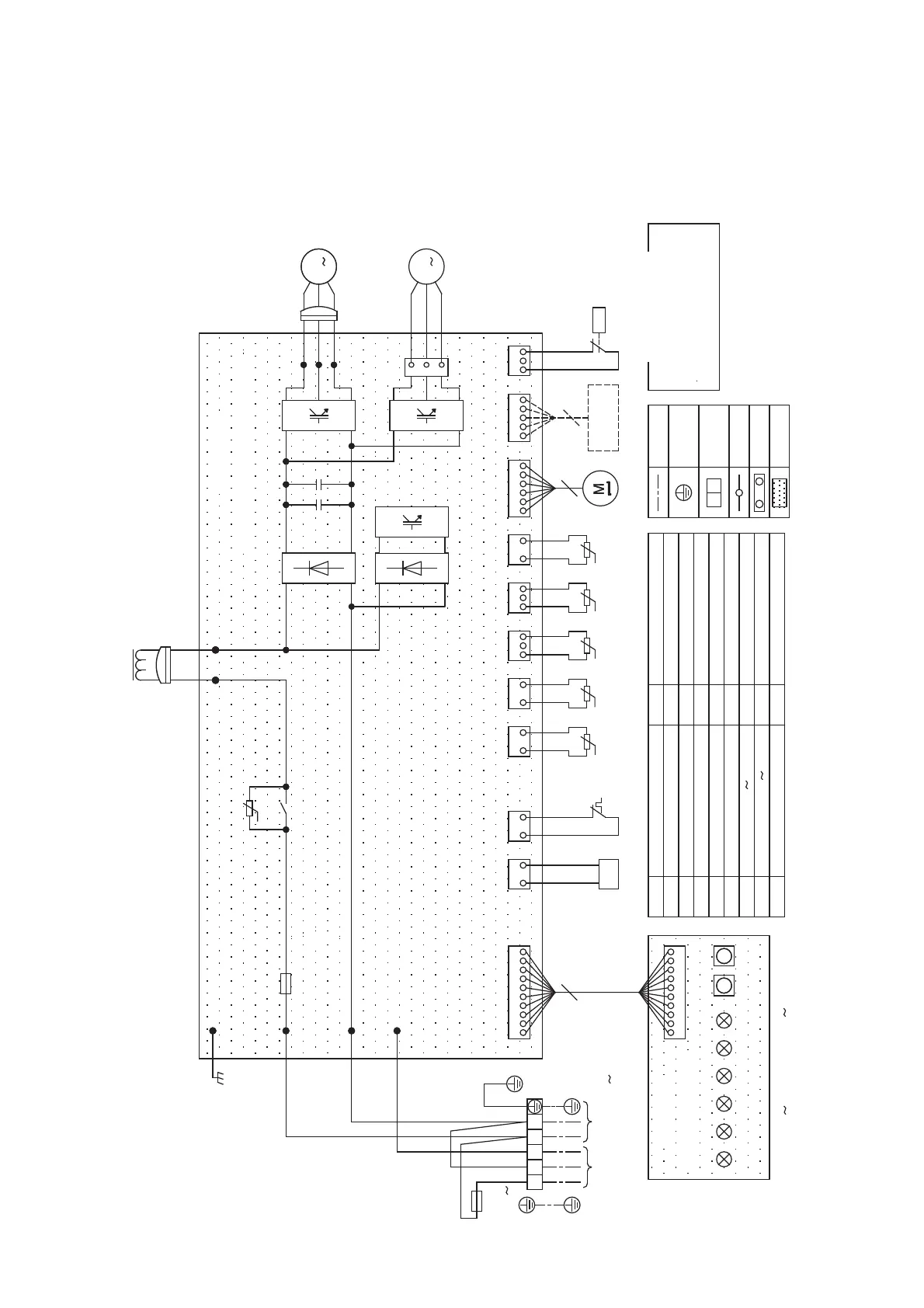
4 WIRING DIAGRAM
4-1. RAV-GP561ATW*
FM
49C
PMV
TS
TD
TE
TO
TB01
Parts name
Fan Motor
Thermostat for Compressor
Pulse Motor Valve
Pipe temp. sensor (Suction)
Pipe temp. sensor (Discharge)
Heat exchange temp. sensor
Air temp. sensor
Terminal block
Field wiring
Protective
Terminal
Terminal
Connector
P.C. board
Fuse 25 A 250 V
Compressor
High pressure switch
***
CM
F01
63H
20SF 4-way valve coil
CN Connector
Fuse T6.3 A 250 V
F-IU
TL Liquid temp. sensor
1.For D800 D805 and SW01 SW02,
re
fer to the installation manual.
SW01 SW02
+
-
-
+
+
+
MS
CM
FM
L-1
20SF
POWER SUPPLYTo INDOOR UNIT
TB01
12
3
L
N
OPTION
PMV
65
MCC-1768
Outdoor Control P.C. board
Symbol Parts name
TLTSTDTETO
(WHI)
CN604
(WHI)
CN603
(WHI)
CN601
(WHI)
CN600CN602
(YEL)
t°t°t°
t°
121 2
t°
CN500
(BLU)
213
213 1212 1 2
CN704
(WHI)
63H
P>
49C
123456
t°
CN700
(WHI) (GRN)
CN501
(BLU)
CN806
12345
3
MS
MS
3
WHI
RED
BLK
RED
WHI
BLK
WHI
WHI
ORN
WHI
BLK
BLK
-
+
Reactor
Symbol
(WHI)
CN807
12345678910
D803
(YEL) (YEL)
D804
(YEL)
D802
(YEL)
D801
(YEL)
508D008D
(GRN)
10
MCC-1646
Display P.C. board
block
earth
YEL: YELLOW
WHI: WHITE
GRN: GREEN
GRY: GRAY
RED: RED
BLU: BLUE
BLK: BLACK
Color Indication
110
9
2345678
CN01(WHI)
P07
P01
P02
P03
CN300
(WHI)
P05
P06
P04
P16
P17
312
L-1
220 - 240 V 50 Hz
1
2
3
ORN: ORANGE
BLK
BLK
WHI
250 V
T6.3 A
F-IU
F01
 Loading...