EasyManua.ls Logo

Toshiba RAV-GP801ATW-E User Manual

Toshiba RAV-GP801ATW-E
131 pages
To Next Page IconTo Next Page
To Previous Page IconTo Previous Page
Page #4 background imageLoading...
Page #4 background image
4
SAFETY CAUTION
Please read carefully through these instructions that contain important information which complies with the
“Machinery Directive” (Directive 2006/42/EC), and ensure that you understand them.
Some of the details provided in these instructions differ from the service manual, and the instructions provided here
take precedence.
Generic Denomination: Air Conditioner
Definition of Qualified Installer or Qualified Service Person
The air conditioner must be installed, maintained, repaired and removed by a qualified installer or qualified service
person.
When any of these jobs is to be done, ask a qualified installer or qualified service person to do them.
A qualified installer or qualified service person is an agent who has the qualifications and knowledge described in
the table below.
Agent Qualifications and knowledge which the agent must have
Qualified installer
(*1)
The qualified installer is a person who installs, maintains, relocates and removes the air conditioners
made by Toshiba Carrier Air-conditioning Europe Sp. z o.o. He or she has been trained to install, main-
tain, relocate and remove the air conditioners made by Toshiba Carrier Air-conditioning Europe
Sp. z o.o. or, alternatively, he or she has been instructed in such operations by an individual or individuals
who have been trained and is thus thoroughly acquainted with the knowledge related to these operations.
The qualified installer who is allowed to do the electrical work involved in installation, relocation and re-
moval has the qualifications pertaining to this electrical work as stipulated by the local laws and regula-
tions, and he or she is a person who has been trained in matters relating to electrical work on the air
conditioners made by Toshiba Carrier Air-conditioning Europe Sp. z o.o. or, alternatively, he or she has
been instructed in such matters by an individual or individuals who have been trained and is thus thor-
oughly acquainted with the knowledge related to this work.
The qualified installer who is allowed to do the refrigerant handling and piping work involved in installation,
relocation and removal has the qualifications pertaining to this refrigerant handling and piping work as
stipulated by the local laws and regulations, and he or she is a person who has been trained in matters
relating to refrigerant handling and piping work on the air conditioners made by Toshiba Carrier Air-
conditioning Europe Sp. z o.o. or, alternatively, he or she has been instructed in such matters by an indi-
vidual or individuals who have been trained and is thus thoroughly acquainted with the knowledge related
to this work.
The qualified installer who is allowed to work at heights has been trained in matters relating to working at
heights with the air conditioners made by Toshiba Carrier Air-conditioning Europe Sp. z o.o. or, alterna-
tively, he or she has been instructed in such matters by an individual or individuals who have been trained
and is thus thoroughly acquainted with the knowledge related to this work.
Qualified service
person (*1)
The qualified service person is a person who installs, repairs, maintains, relocates and removes the air
conditioners made by Toshiba Carrier Air-conditioning Europe Sp. z o.o. He or she has been trained to
install, repair, maintain, relocate and remove the air conditioners made by Toshiba Carrier Air-
conditioning Europe Sp. z o.o. or, alternatively, he or she has been instructed in such operations by an
individual or individuals who have been trained and is thus thoroughly acquainted with the knowledge re-
lated to these operations.
The qualified service person who is allowed to do the electrical work involved in installation, repair, relo-
cation and removal has the qualifications pertaining to this electrical work as stipulated by the local laws
and regulations, and he or she is a person who has been trained in matters relating to electrical work on
the air conditioners made by Toshiba Carrier Air-conditioning Europe Sp. z o.o. or, alternatively, he or she
has been instructed in such matters by an individual or individuals who have been trained and is thus thor-
oughly acquainted with the knowledge related to this work.
The qualified service person who is allowed to do the refrigerant handling and piping work involved in in-
stallation, repair, relocation and removal has the qualifications pertaining to this refrigerant handling and
piping work as stipulated by the local laws and regulations, and he or she is a person who has been
trained in matters relating to refrigerant handling and piping work on the air conditioners made by Toshiba
Carrier Air-conditioning Europe Sp. z o.o. or, alternatively, he or she has been instructed in such matters
by an individual or individuals who have been trained and is thus thoroughly acquainted with the knowl-
edge related to this work.
The qualified service person who is allowed to work at heights has been trained in matters relating to
working at heights with the air conditioners made by Toshiba Carrier Air-conditioning Europe Sp. z o.o.
or, alternatively, he or she has been instructed in such matters by an individual or individuals who have
been trained and is thus thoroughly acquainted with the knowledge related to this work.

Table of Contents

Other manuals for Toshiba RAV-GP801ATW-E

Question and Answer IconNeed help?

Do you have a question about the Toshiba RAV-GP801ATW-E and is the answer not in the manual?

Toshiba RAV-GP801ATW-E Specifications

General IconGeneral
BrandToshiba
ModelRAV-GP801ATW-E
CategoryAir Conditioner
LanguageEnglish

Summary

Safety Cautions and Guidelines

Qualified Installer and Service Person Definition

Defines requirements for qualified installers and service personnel for AC operations.

Protective Gear Requirements

Details necessary protective gear for various work tasks to ensure safety.

Unit Warning Indications and Symbols

Explains warning labels, symbols, and general safety precautions for unit operation.

General Safety Precautions

Outlines essential safety measures for installation, maintenance, and repair work.

Technical Specifications

Indoor Unit Specifications

Provides detailed technical specifications for various indoor unit types.

Outdoor Unit Specifications

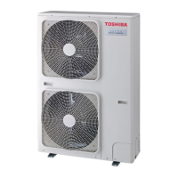
Details technical specifications for the outdoor unit models.

Operation Characteristic Curves

Presents performance graphs showing unit operation based on temperature and speed.

Construction Views and Diagrams

RAV-GP561ATW* External Views

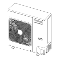
Provides detailed external views and dimensions for the RAV-GP561ATW* outdoor unit.

RAV-GP801ATW* External Views

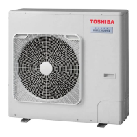
Provides detailed external views and dimensions for the RAV-GP801ATW* outdoor unit.

Branch Pipe Details

Details dimensions and models for branch pipes used in twin systems.

Outdoor Unit Refrigerant Cycle Diagram

GP561 Refrigerant Cycle Diagram

Illustrates the refrigerant flow and component layout for the GP561 model.

GP801 Refrigerant Cycle Diagram

Illustrates the refrigerant flow and component layout for the GP801 model.

Wiring Diagrams

RAV-GP561ATW* Wiring Diagram

Shows the electrical wiring connections and component layout for the RAV-GP561ATW* outdoor unit.

RAV-GP801ATW* Wiring Diagram

Shows the electrical wiring connections and component layout for the RAV-GP801ATW* outdoor unit.

Electrical Parts Specifications

Outdoor Unit Electrical Parts

Lists electrical components and their specifications for outdoor unit models.

Winding Resistance of Outdoor Unit Main Parts

Provides winding resistance values for key outdoor unit electrical components.

Refrigerant R32 Guidelines

Safety During Installation and Servicing

Details critical safety precautions for handling R32 refrigerant during installation and service.

Refrigerant Piping Installation

Covers requirements and procedures for installing refrigerant piping.

Piping Materials and Joints Used

Specifies approved piping materials and joint types for R32 refrigerant.

Recharging of Refrigerant Procedure

Outlines the procedure for recharging refrigerant into the system.

Brazing of Pipes

Describes materials, flux, and procedures for brazing refrigerant pipes.

Materials for Brazing

Lists recommended brazing filler materials.

Flux Usage and Types

Explains the purpose and types of flux used in brazing.

Brazing Process Details

Details the brazing process, including oxidation prevention.

Re-use Piping Instructions (R22/R407C to R32)

Provides guidelines for reusing existing R22 or R407C piping with R32 systems.

Basic Conditions for Reusing Pipes

Lists essential conditions for reusing existing refrigerant pipes.

Restricted Items for Pipe Reuse

Identifies cases where existing pipes cannot be reused.

Branching Pipe for Simultaneous Operation

Specifies reuse conditions for branch pipes in twin systems.

Curing of Pipes Procedure

Describes procedures for curing pipes when units are disconnected.

Final Installation Checks for Existing Pipes

Outlines final checks for existing pipe installations.

Handling of Existing Pipe Precautions

Details precautions for handling existing refrigerant pipes.

Charging Additional Refrigerant

Provides guidelines for adding refrigerant to the system.

Assumed Gas Leak Procedure

Describes procedures for charging refrigerant when a gas leak is assumed.

Limits for Additional Refrigerant Charge

Specifies limits for additional refrigerant charging.

Cautions for Additional Refrigerant Charging

Lists important cautions for charging additional refrigerant.

General Safety Precautions for R32 Refrigerant

Covers essential safety measures when working with R32 refrigerant.

Refrigerant Recovery Procedures

Details procedures for recovering refrigerant safely.

Decommissioning Procedures

Explains the safe decommissioning process for the unit.

Equipment Labelling Requirements

Specifies requirements for equipment labelling after decommissioning.

Circuit Configuration and Control Specifications

Outdoor Unit Control Systems

Describes the control functions and specifications of the outdoor unit.

Print Circuit Board (MCC-1768) Details

Details the Print Circuit Board (MCC-1768) for outdoor unit control.

Print Circuit Board (MCC-1705) Details

Details the Print Circuit Board (MCC-1705) for outdoor unit control.

Outline of Main Controls

Explains the main control logic and operations of the unit.

PMV (Pulse Motor Valve) Control

Describes the control mechanism of the Pulse Motor Valve (PMV).

Discharge Temperature Release Control

Explains the control logic for releasing discharge temperature.

Outdoor Fan Revolution Number Control

Details the control logic for the outdoor fan's revolution speed.

Cooling Fan Control

Explains fan speed control during cooling operations.

Heating Fan Control

Explains fan speed control during heating operations.

Defrost Control Logic

Describes the defrost cycle logic and conditions.

Short Interrupted Operation Preventive Control

Explains the control to prevent short interruptions for compressor protection.

Electrical Current Release Control

Details the control logic for managing electrical current release.

Heat Sink Temperature Detection Control

Explains the control logic based on heat sink temperature detection.

Electrical Current Release Value Shift Control

Describes control for shifting electrical current release values.

Over-Current Protective Control

Explains the over-current protection mechanism for the unit.

High-Pressure Switch & Compressor Case Thermostat Control

Details control related to high-pressure switch and compressor case thermostat.

High-Pressure Release Control

Explains the control logic for high-pressure release.

Coil Heating Control

Describes the coil heating control function for compressor protection.

Troubleshooting Guide

Summary of Troubleshooting

Provides an overview of troubleshooting procedures, required tools, and initial checks.

Troubleshooting Procedures

Details troubleshooting steps based on error codes and indicator lights.

Troubleshooting Judgment Outline

Explains how to judge troubleshooting status using lamp indications and check codes.

Troubleshooting Other Issues

Covers troubleshooting for issues not indicated by specific check codes.

Remote Controller Monitor Function

Explains how to use the remote controller's monitor function to check sensor data.

Outdoor Unit Check Code List

Lists error codes, their causes, and troubleshooting steps for outdoor unit issues.

Diagnostic Procedure for Outdoor Unit Check Codes

Provides step-by-step diagnostic procedures for outdoor unit check codes using LED indications.

Setup and Configuration

Calling Check Code History

Describes how to retrieve past error code history from the indoor unit using the remote controller.

Outdoor Unit Operations and Settings

Details operations and settings accessible via the outdoor unit's service switches and LEDs.

Various Settings via Outdoor Unit

Explains various configurable settings via outdoor unit service switches like pipe settings and fan control.

Service Switch Setting Procedure

Details the procedure for configuring settings using service switches SW01 and SW02.

Service Support Functions (LED/Switch)

Covers functions accessed via LED display and service switches for maintenance and diagnostics.

LED Display Switching (SW01/SW02 Operation)

Explains how to switch LED display contents using SW01 and SW02 for diagnostics.

Refrigerant Leak Detection Function

Describes the function for detecting refrigerant leaks using LED indicators.

Maintenance Inspections Special Operations

Details special maintenance and inspection operations using service switches.

Outdoor Application Operation

Explains outdoor unit application operations like peak-cut and night mode settings.

Address Setup Procedures

Address Setup Procedure

Outlines the procedure for setting unit addresses and group configurations for networked units.

Address Setup & Group Control Concepts

Defines terms and concepts related to unit addressing and group control configurations.

System Configuration Examples

Illustrates different system configurations for indoor and outdoor units in group setups.

Automatic Address Setup Example

Shows an example of automatic address setup when units are initially connected.

Remote Controller Wiring Instructions

Details the wiring instructions and precautions for the remote controller connection.

Manual Address Setup via Remote Controller

Explains how to manually set unit addresses using the remote controller.

Indoor Unit Position Confirmation by Address

Describes how to confirm the position and address of indoor units within a group.

Service P.C. Board Replacement

RAV-GP561ATW* Service P.C. Board Replacement

Provides replacement steps for the service P.C. board on the RAV-GP561ATW* model.

Compressor Exchange Procedure

Compressor Exchange Procedure Outline

Outlines the general procedure for safely exchanging the compressor unit.

Detachment and Reassembly Procedures

RAV-GP561ATW* Detachment Procedures

Details the step-by-step procedure for detaching various components of the RAV-GP561ATW*.

RAV-GP801ATW* Detachment Procedures

Details the step-by-step procedure for detaching various components of the RAV-GP801ATW*.

Exploded Views and Parts Lists

Outdoor Unit Exploded View and Parts List

Provides an exploded view and list of parts for the outdoor unit.

Inverter Assembly Exploded View and Parts List

Provides an exploded view and list of parts for the inverter assembly.

Related product manuals