10 18-GE08D1-7
Installer’s Guide
2. The selection of wire and fuse sizes should be made
according to the Minimum Branch Circuit Ampacity
and the Maximum Overcurrent Device listed on the
unit nameplate.
3. Field wiring diagrams for electric heaters and unit
accessories are shipped with the accessory.
4. Wiring must conform to National and Local
codes. Ground unit per Local codes with good
safety procedures.
If an electric heater is not installed, the Knockout
Plate provided in the Accessory Kit MUST be in-
stalled on the air handler and the conduit termi-
nated to it. The electrical connections are made
using the two power leads and ground wire con-
nections which are located near the discharge of
the blower.
Openings where field wiring en-
ters the cabinet must be completely sealed.
Location of power entry is shown on the outline
drawing. Use 2.5" clear stickers to seal all unused
electrical knockouts.
NOTE: If air handler is used with or without a heater,
the 7/8" electrical entry hole as well as any other
cabinet penetrations must be sealed air tight.
I. CONTROL WIRING
1. Connect wiring between indoor unit, outdoor unit
and Comfort Control. The use of color-coded low-
voltage wires is recommended.
2. Field wiring diagrams are provided which show the
low voltage wiring hook-up for a single speed
cooling only system (with supplementary heaters)
and a heat pump system (with supplementary
heaters). Plug in type electrical connectors are
provided for use with supplementary heaters.
IMPORTANT:
When supplementary heaters are installed, inspect to
insure that all packaging material has been removed.
NOTE: Direct drive motors have bearings which are
permanently lubricated and under normal use lubri-
cation is not recommended.
HOOK-UP DIAGRAMS
WARNING
!
TO PREVENT INJURY OR DEATH DUE TO ELECTRICAL
SHOCK OR CONTACT WITH MOVING PARTS, LOCK
UNIT DISCONNECT SWITCH IN OPEN POSITION
BEFORE SERVICING UNIT.
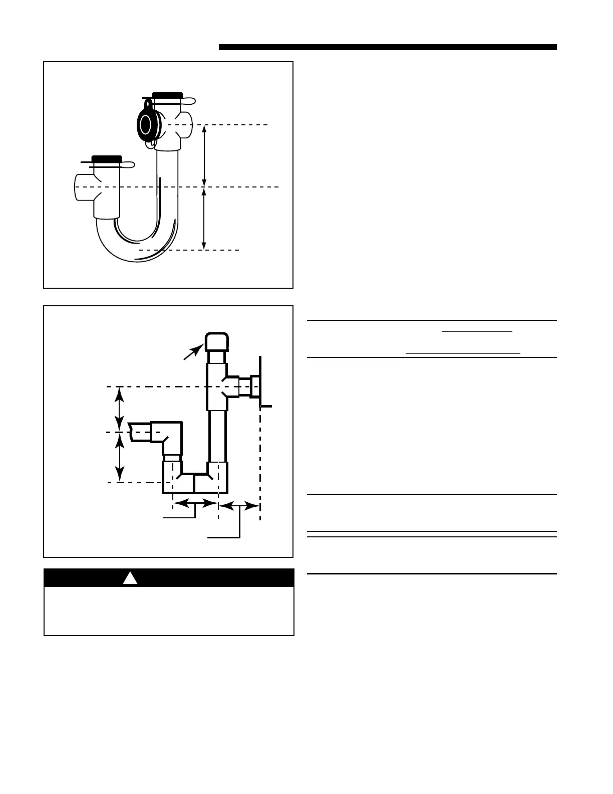
2" MINIMUM
2" MINIMUM
MANUFACTURED TRAPS
EZT-105
t
FIELD FABRICATED TRAP
2" MIN.
2" MIN.
CAP OR PLUG
Trap must be within 4'
of air handler condensate
drain connection.
Close as possible
y
H. ELECTRICAL — POWER WIRING
1. These Air Handlers are shipped from the factory
wired for 230 volts. The units may be wired for 208
volts. Follow instructions on unit wiring diagram lo-
cated on blower housing and in the Service Facts
document included with the unit.

 Loading...
